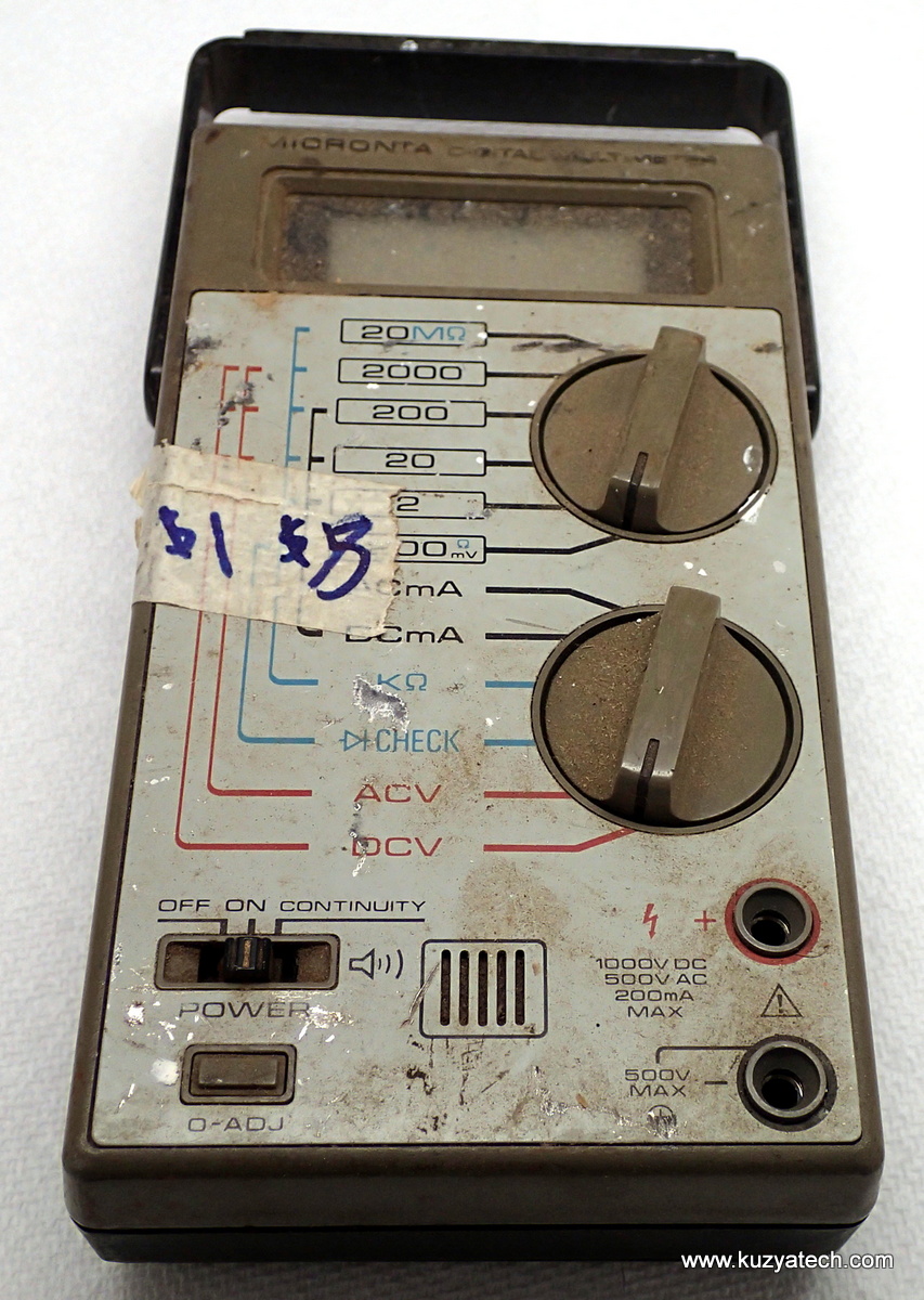
And here is the second part of the $1 multimeter deal from the last Hamfest. Together with Micronta 22-201U analog meter reviewed here I picked up this 3.5 digit digital one of a similar age. The poor thing looks like it had a rather difficult life!
Updated 11/2016
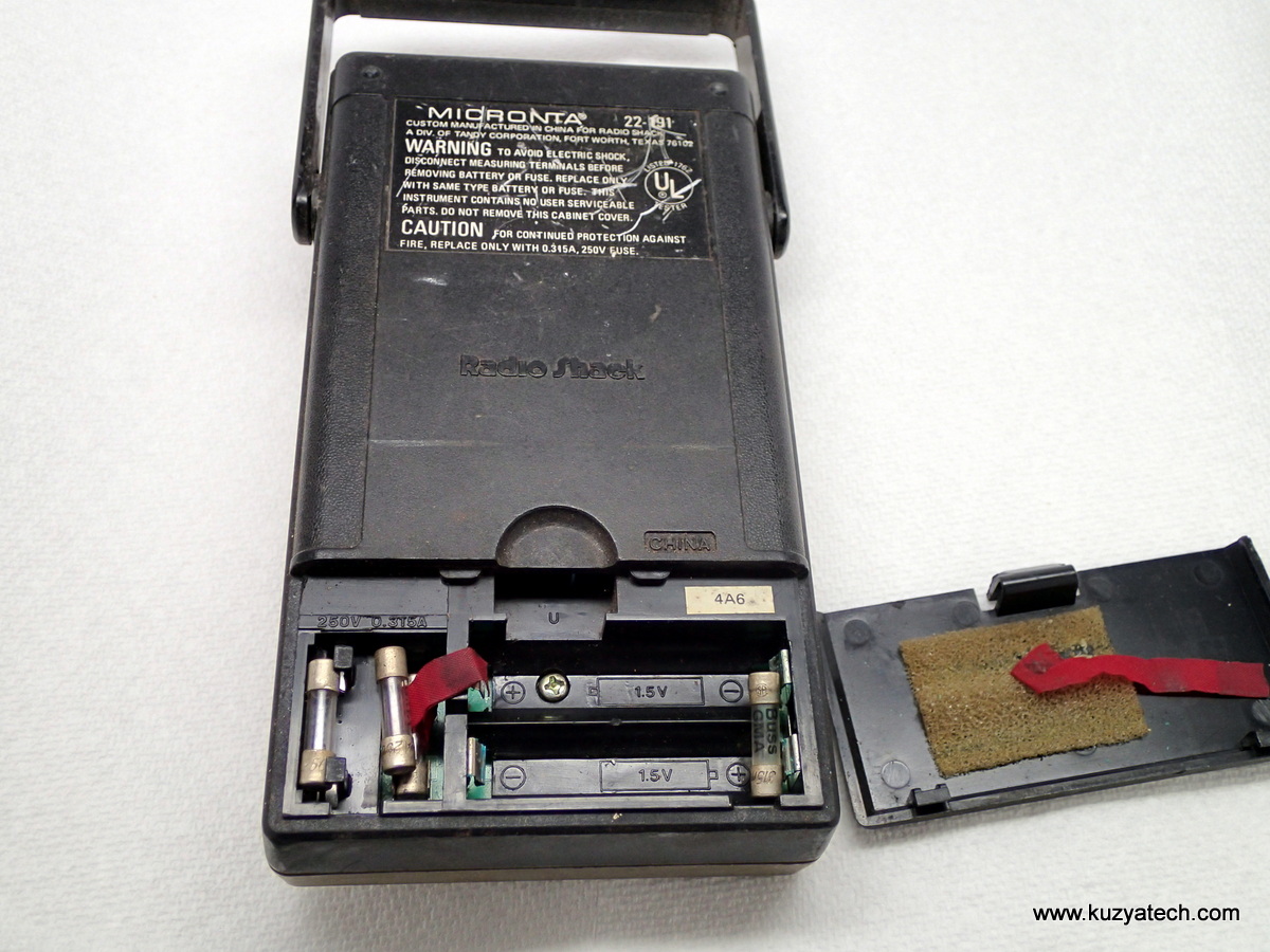
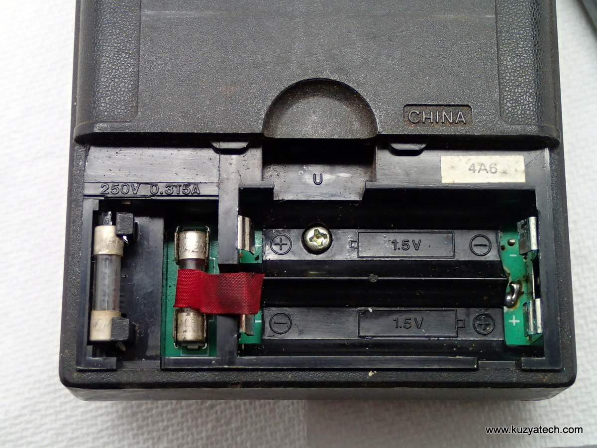
2 AA, not some 9V. And a spare fuse holder
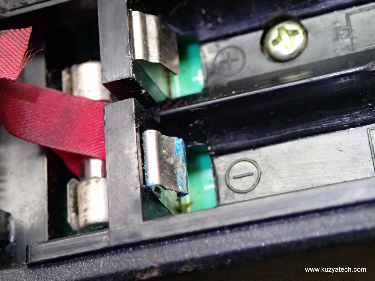
A bit of corrosion on the battery contacts
One screw and a few clips hold things together:
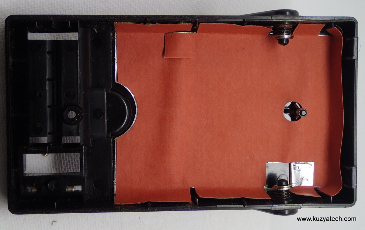
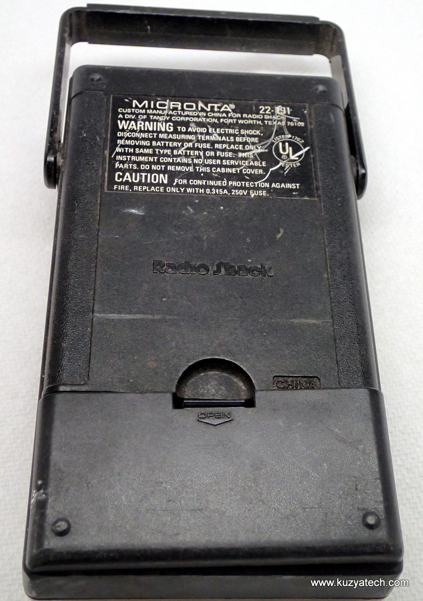
Nicely shielded back cover

Case front- buzzer, shielding
Not much to say safety wise- no board slots, MOVs etc:
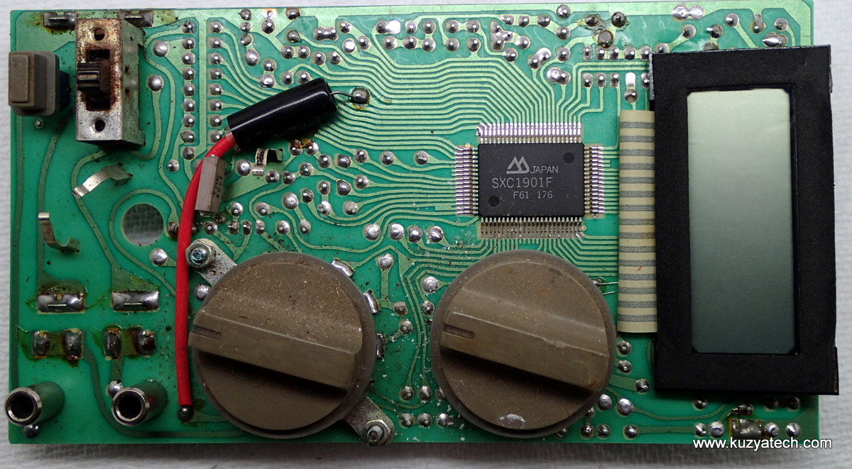

Hand taped traces?
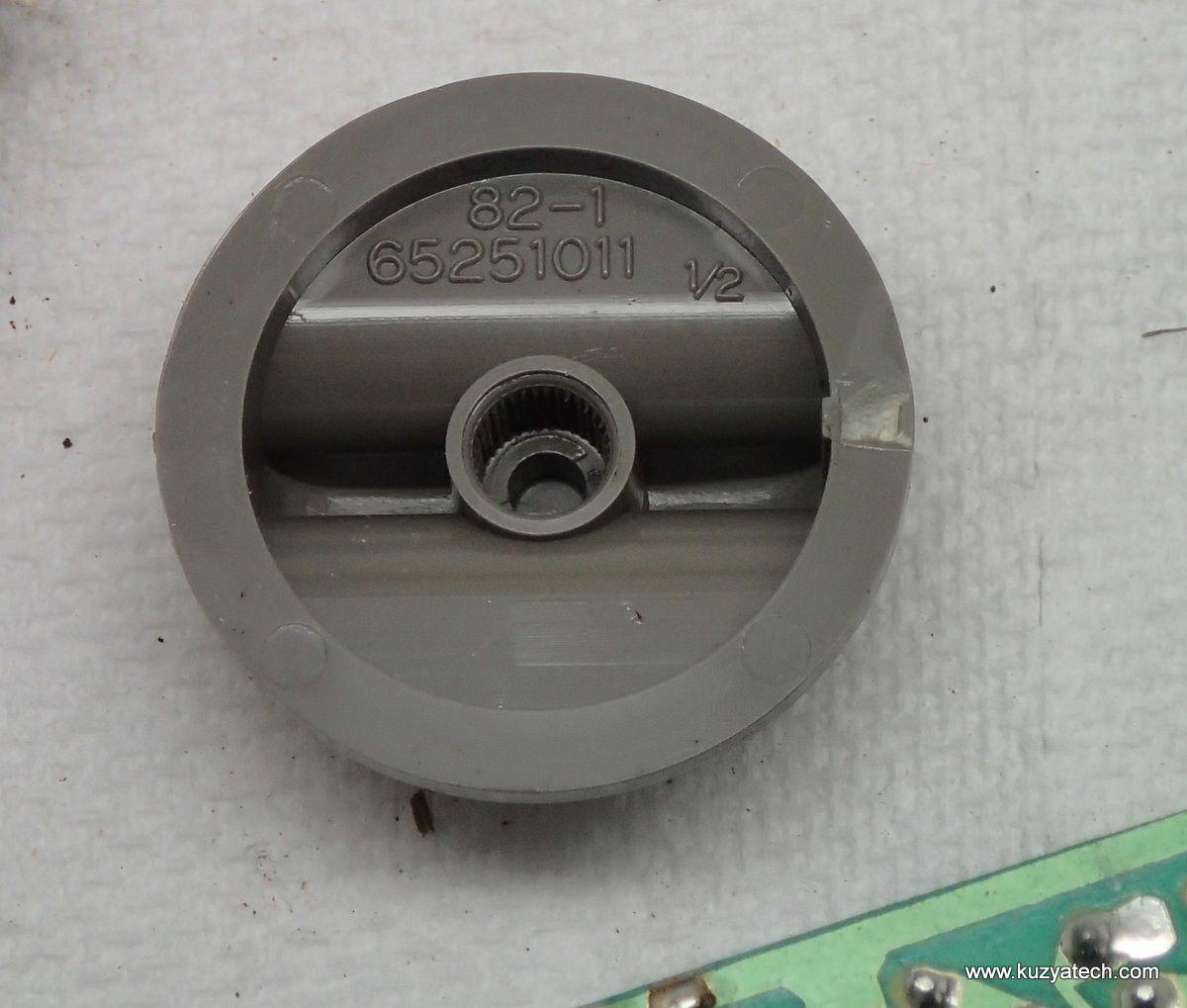
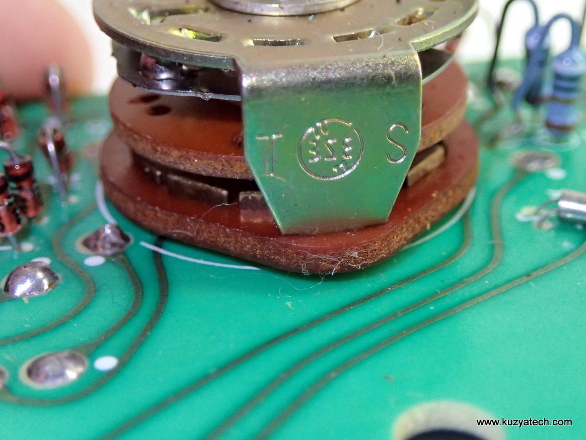
We may have found a datecode? 1982
After cleaning and drying, the meter powered up, but the display segments were very flaky: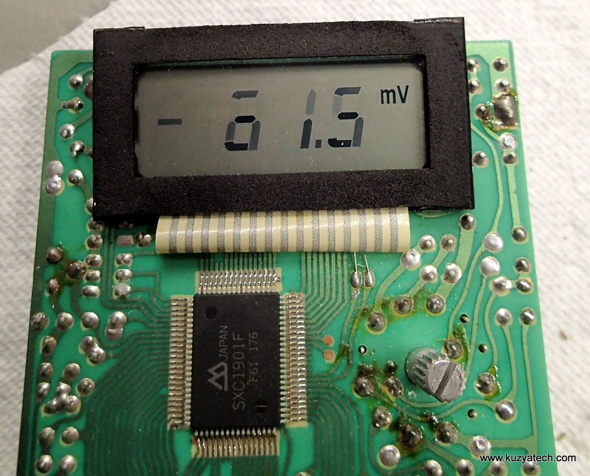
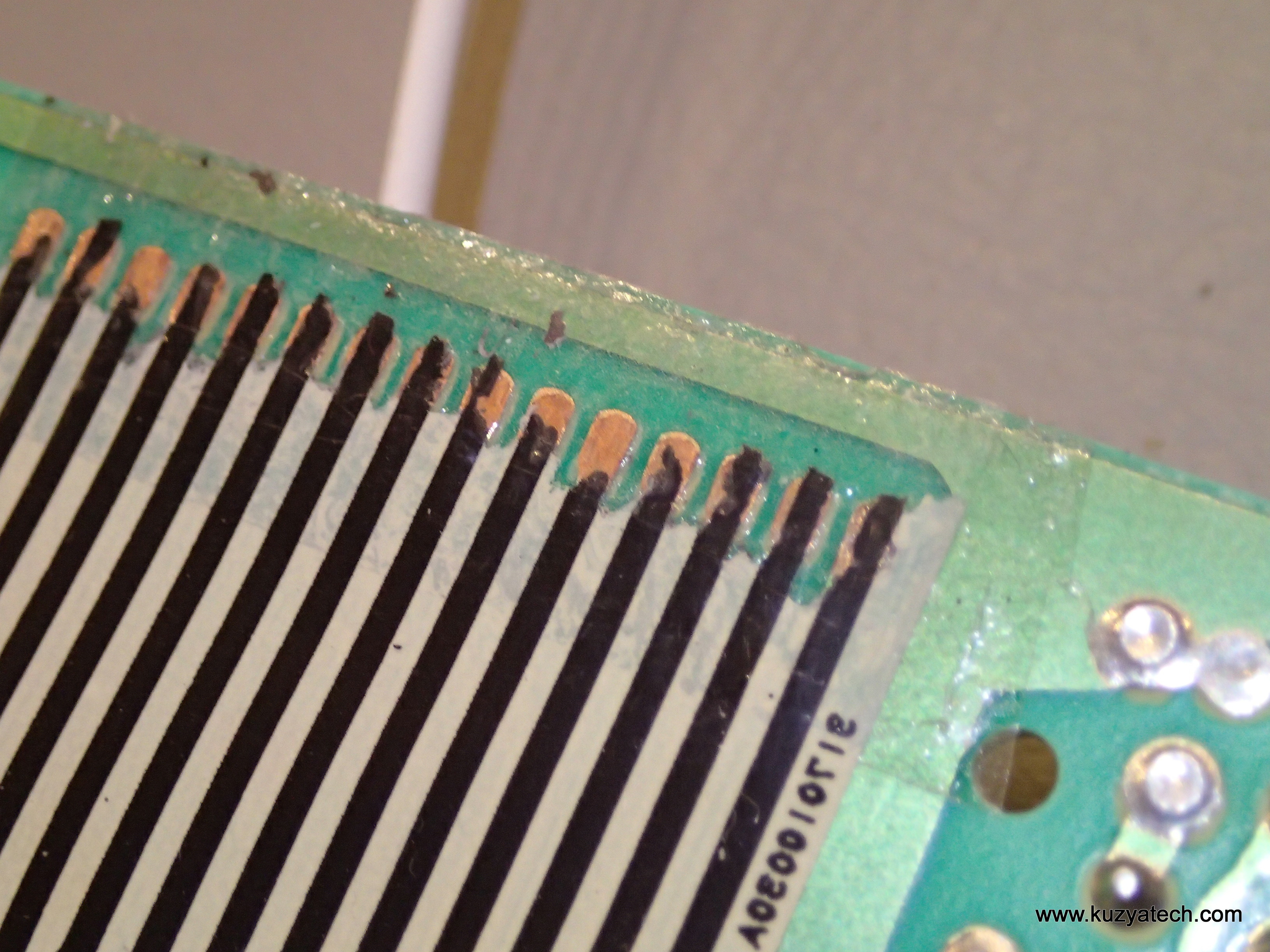
If I wiggled the flex things got better. So I took the display off to see what I can do. Big mistake! The paper-thin flex just peeled off the board and now we have a display that is not connected at all! On the other hand we have another datecode confirmation 82-1: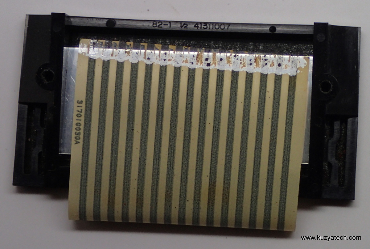
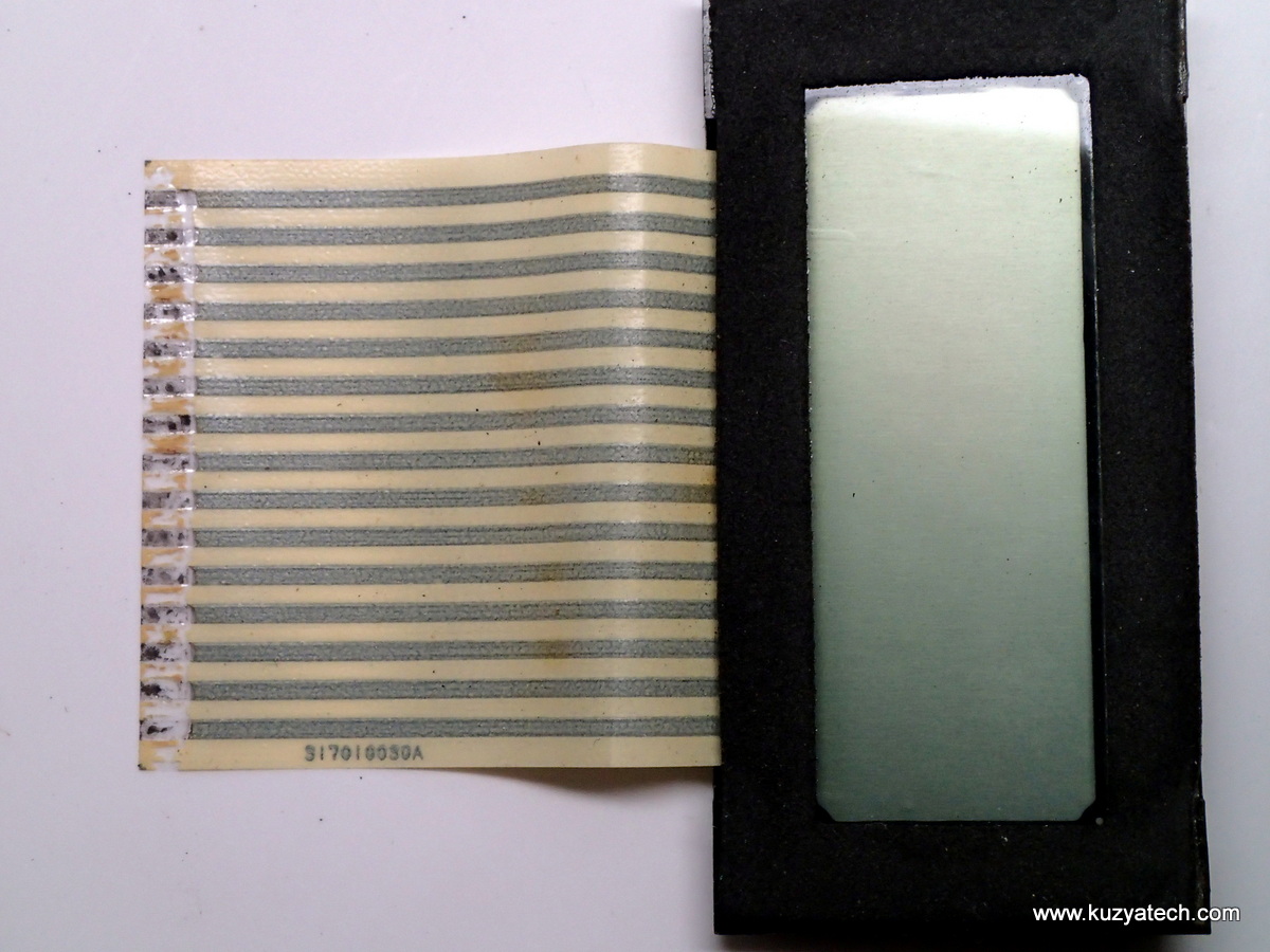
Not sure this damage is reversible- I suppose if somebody sells the conductive tape like this, but what are the odds..
Update 11/2016
Well, it appears things are not that bad. After reading about 3M Z-tape, I got a hold of some. Mine came from Sparkfun, and has since been discontinued. Adafruit has a similar product and also a nice page with details on how it works, but it’s basically a double sticky tape with vertical conductive channels. Kinda like Zstrip used with segmented LCDs but on a much smaller scale.
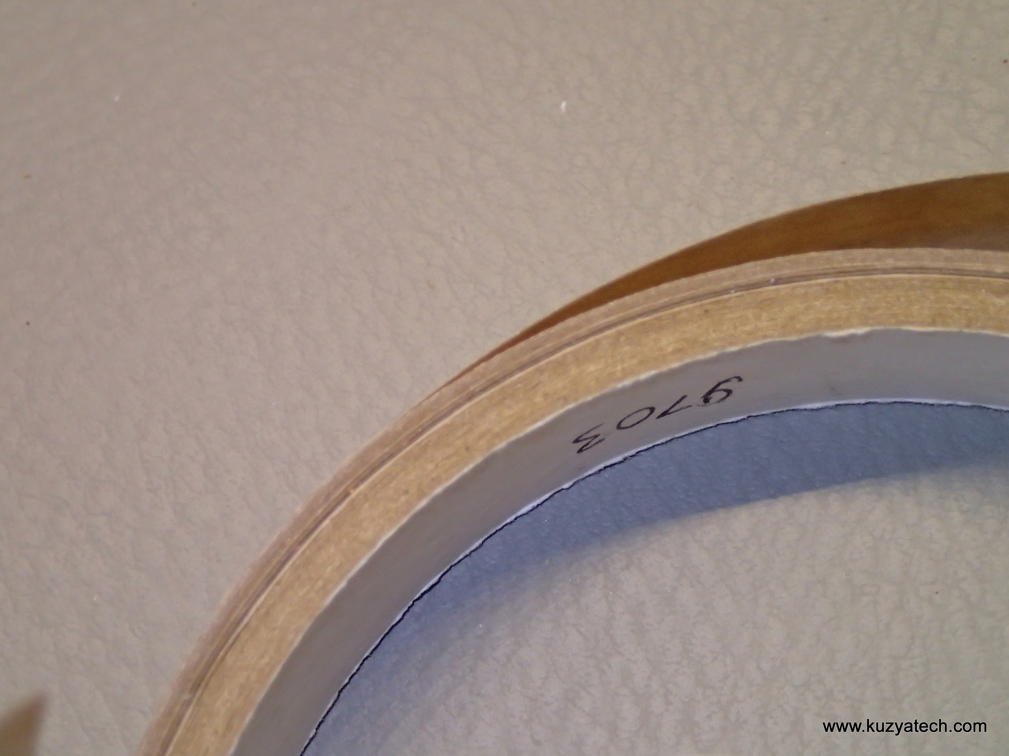
3M 9703 Z-tape
Next step was to clean the junk off the board. Flex side proved to be trickier- I had to carefully dissolve some of the paint on the back to get to more conductive ink traces. After that it was all basically peel and stick:
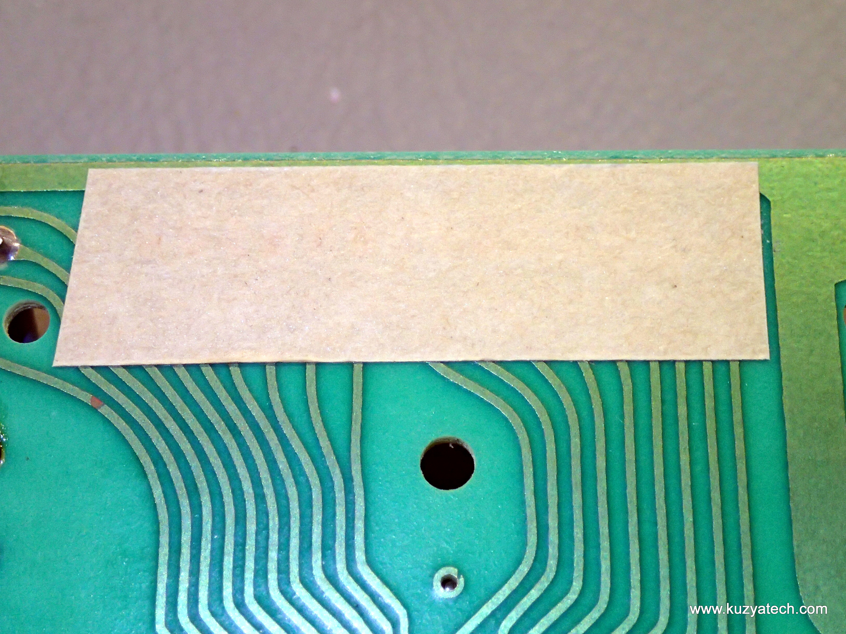
Applying Ztape to the board
Next is the pasting part- remove tape liner, align traces (or what’s left of them) and press:
And finally add a piece of ESD foam to keep things under pressure for better contact
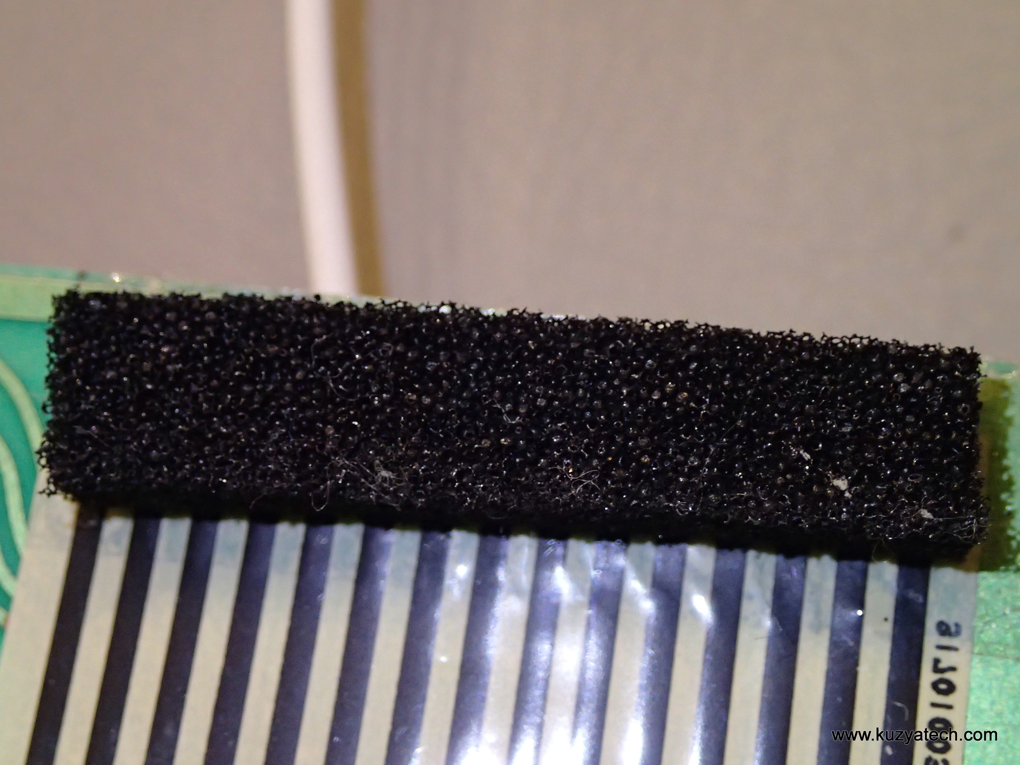
Some ESD foam for even pressure
Reinstall the two screws holding the display, and we now have a readable LCD!
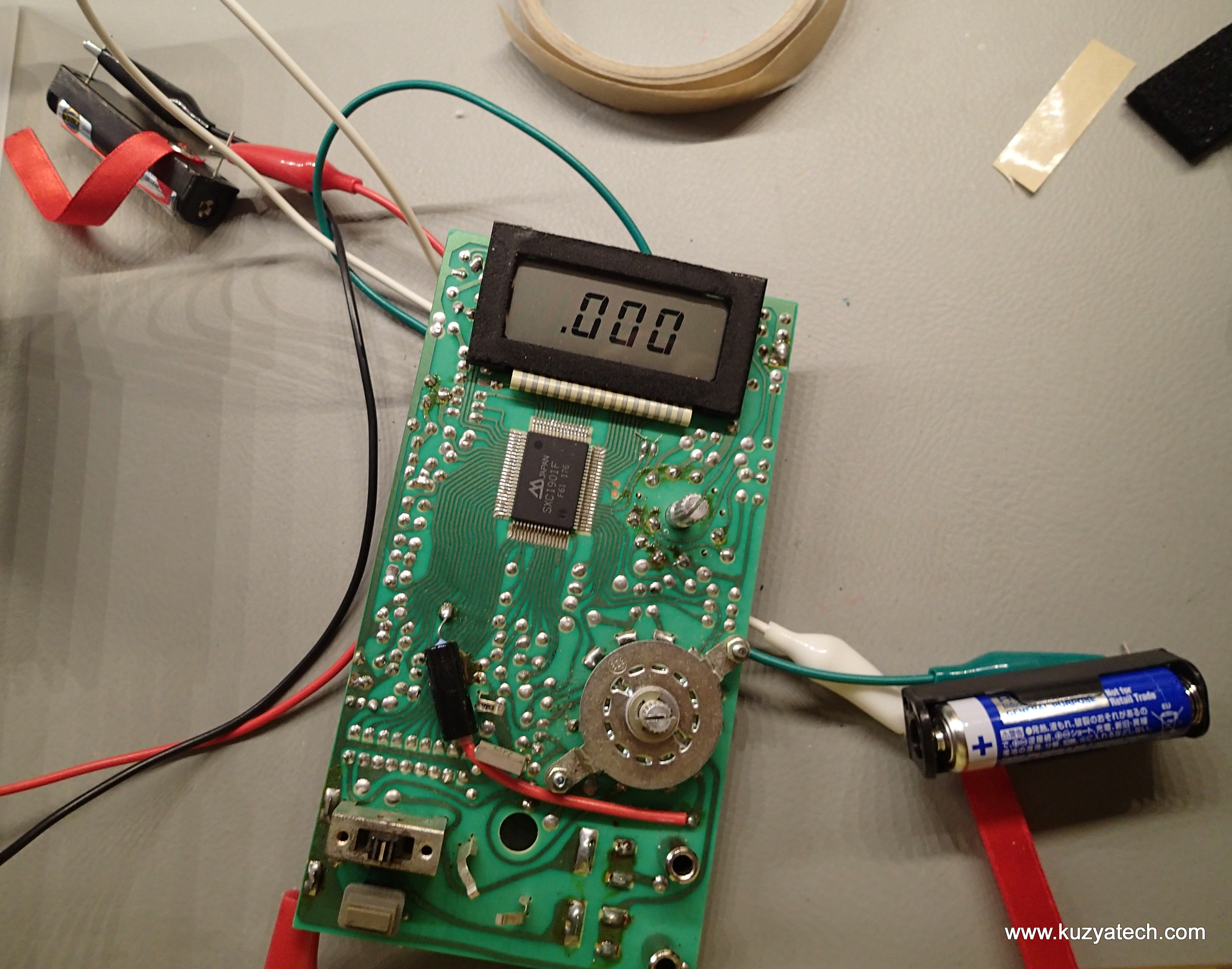
It’s alive!
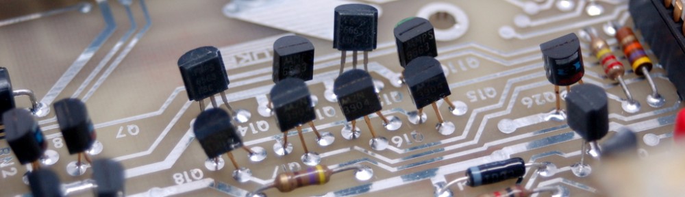
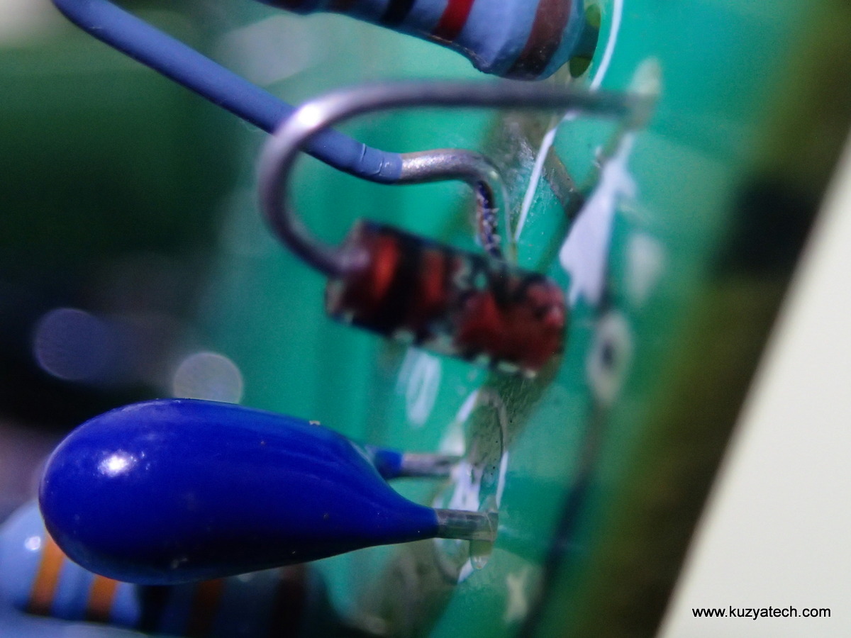
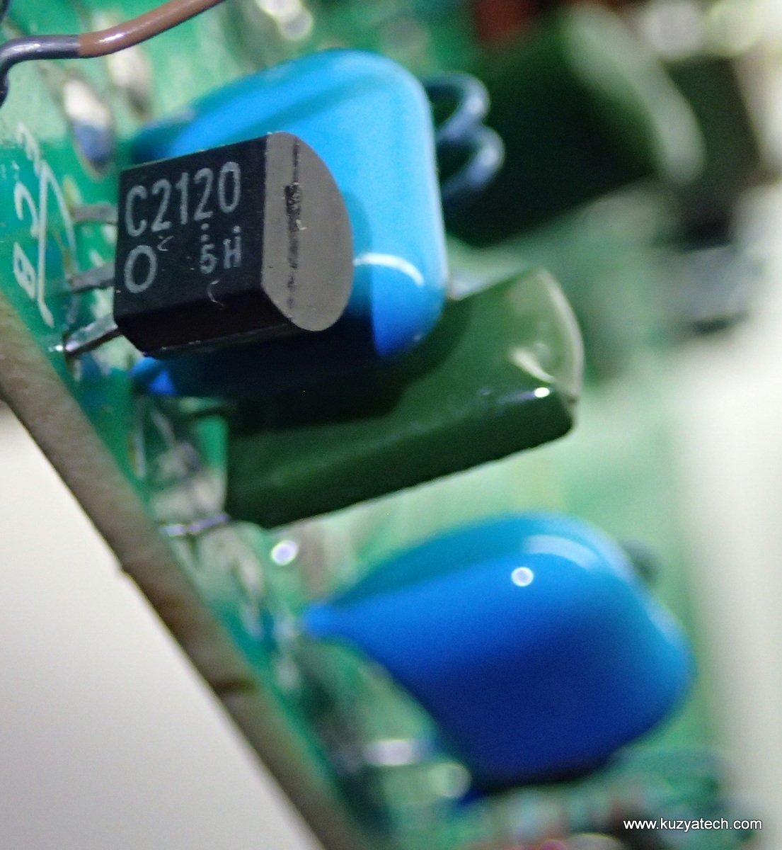
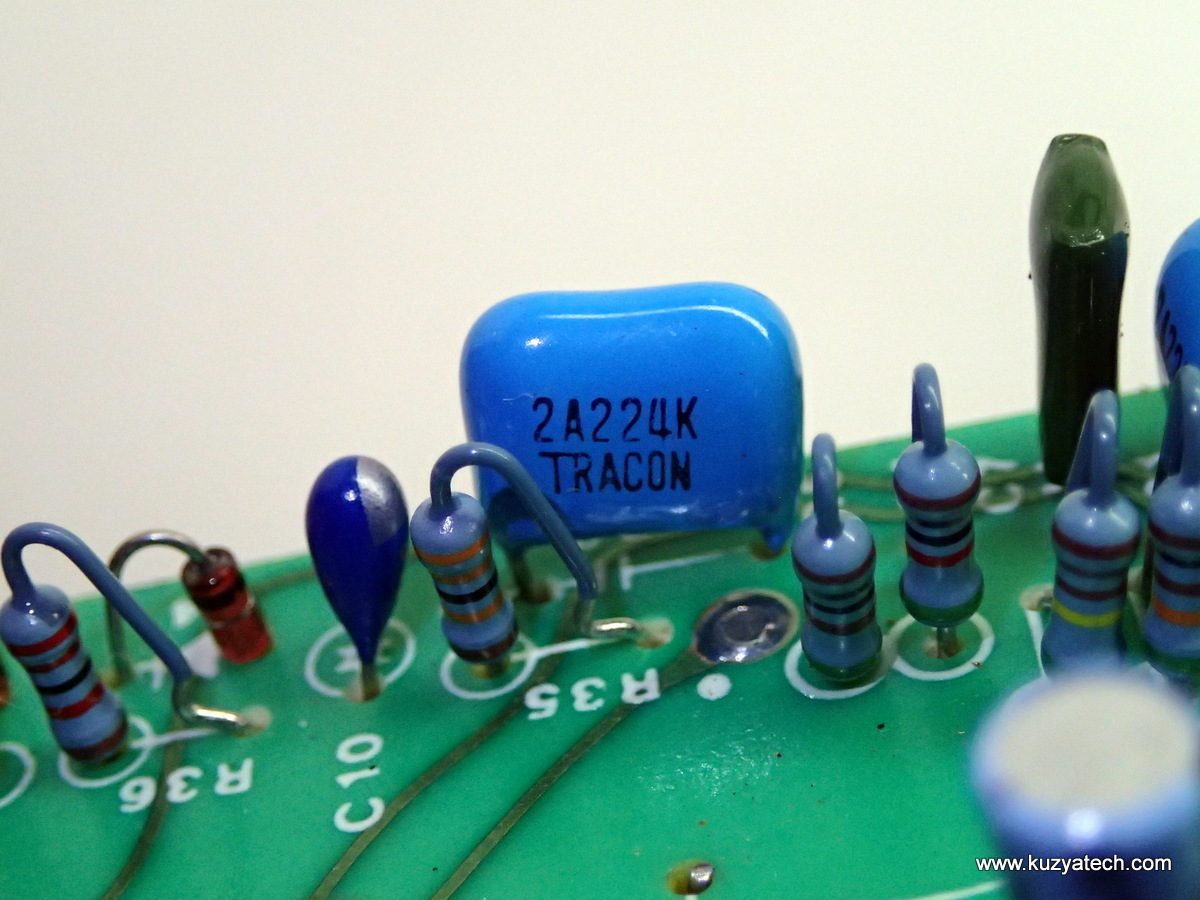
And now for some vintage views:
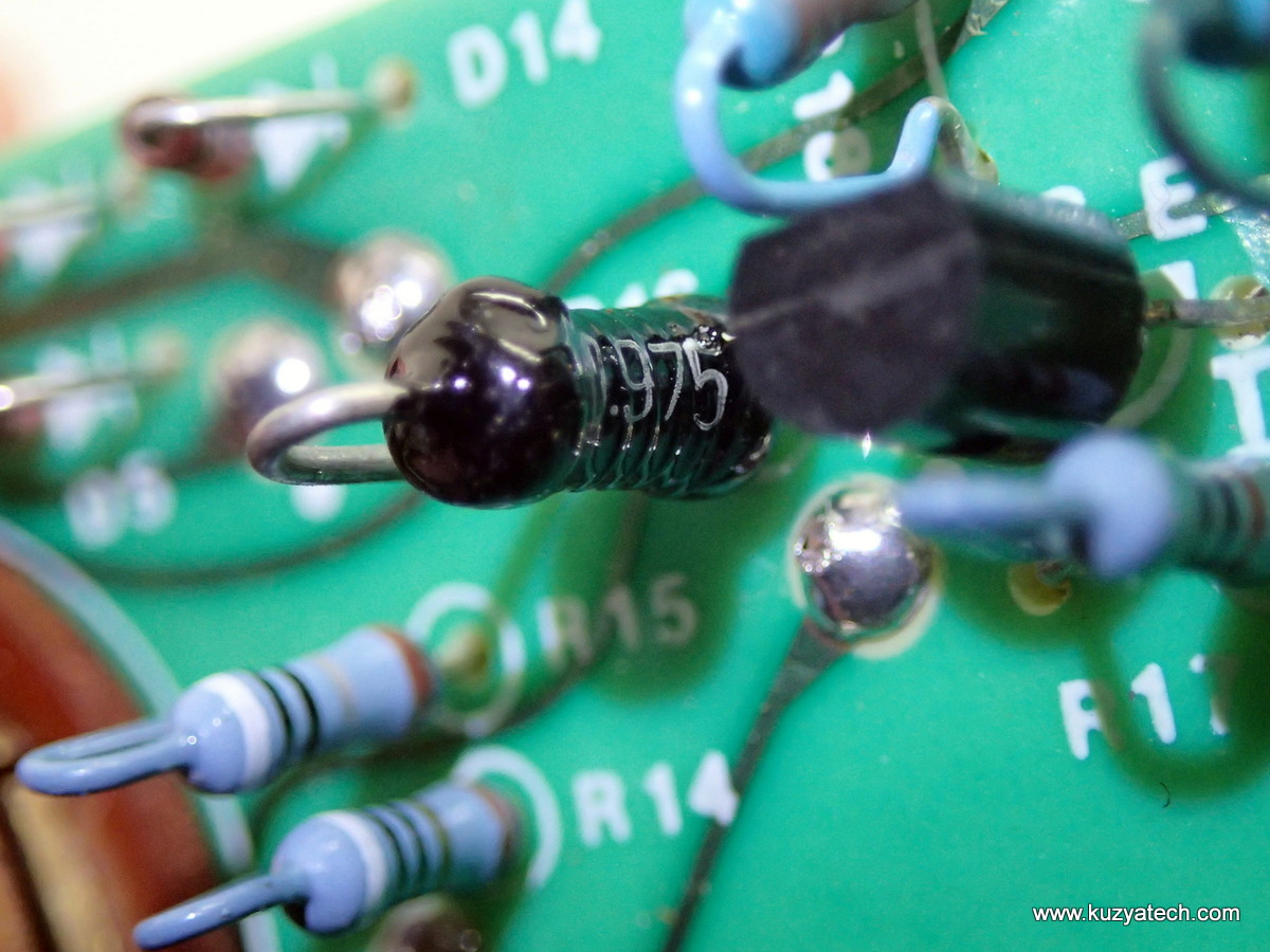
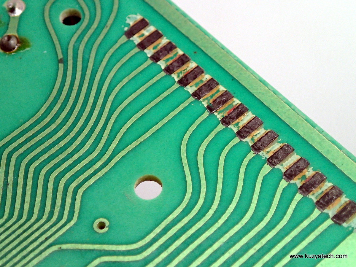
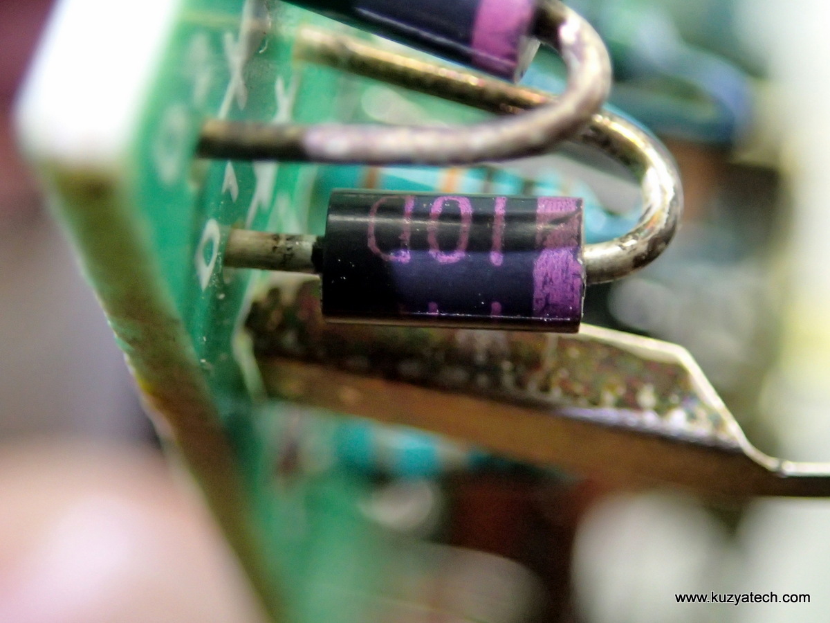
1975 datecode on this wirewound resistor
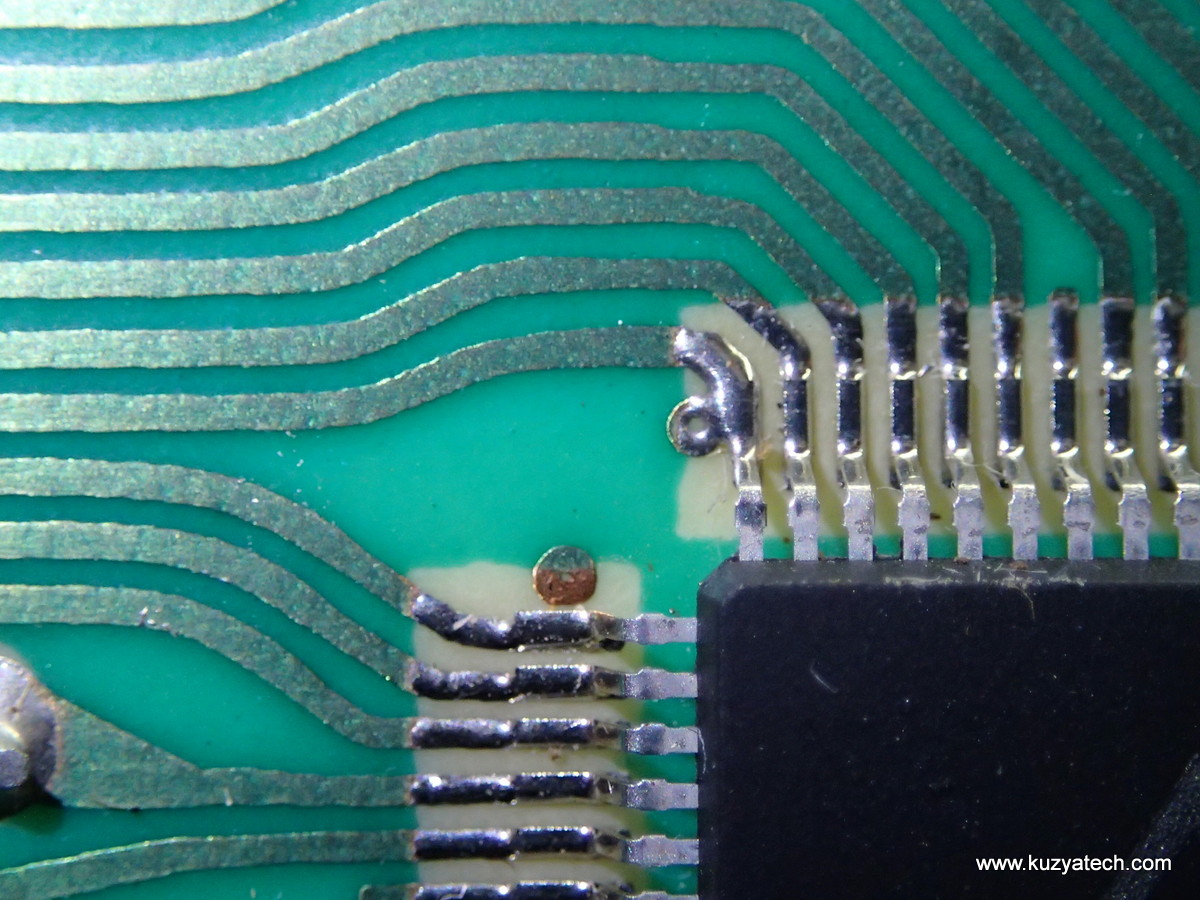
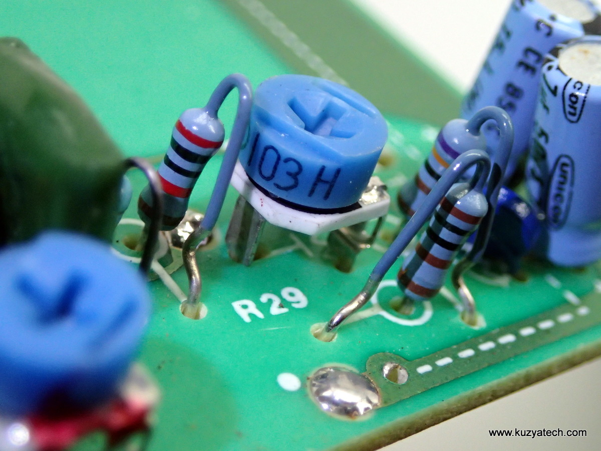
One way to open solder mask


Schematic diagram:

Schematic courtesy user manual
Resources
Pingback: Multimeter Teardowns: the Micronta 22-191 & 22-201U « Adafruit Industries – Makers, hackers, artists, designers and engineers!
Still have mine and its working just fine!
A good old multimeter, i have one and adjusted the onboard reference resistors to make it more accurate, and re-working the mode switch so it does not include the fuse in the resistance ranges.
It helps to get a lower zero ohms on the 200 ohm scale, 0.2 ohms stray is typical with real copper probes.
Safety depends on the user, i have never had even a hint of problems in 30 years of using this multimeter 😀
Perhaps its luck 😀
I got one for 35 years and it worked fine but one month ago it started to indicate wrong measures during AC/DC operations. If I want to measure 120VAC, I have to dial 220 VAC scales in order to match good reading, same thing happen with DC measures. Do you have any idea what is going on with it. I may appreciate your help on this.
SORRY, I MADE A MISTAKE; INSTEAD OF 220 SCALES I MEANT 2000. THANKS
Had mine for 35 years worked fine until had a battery leak.