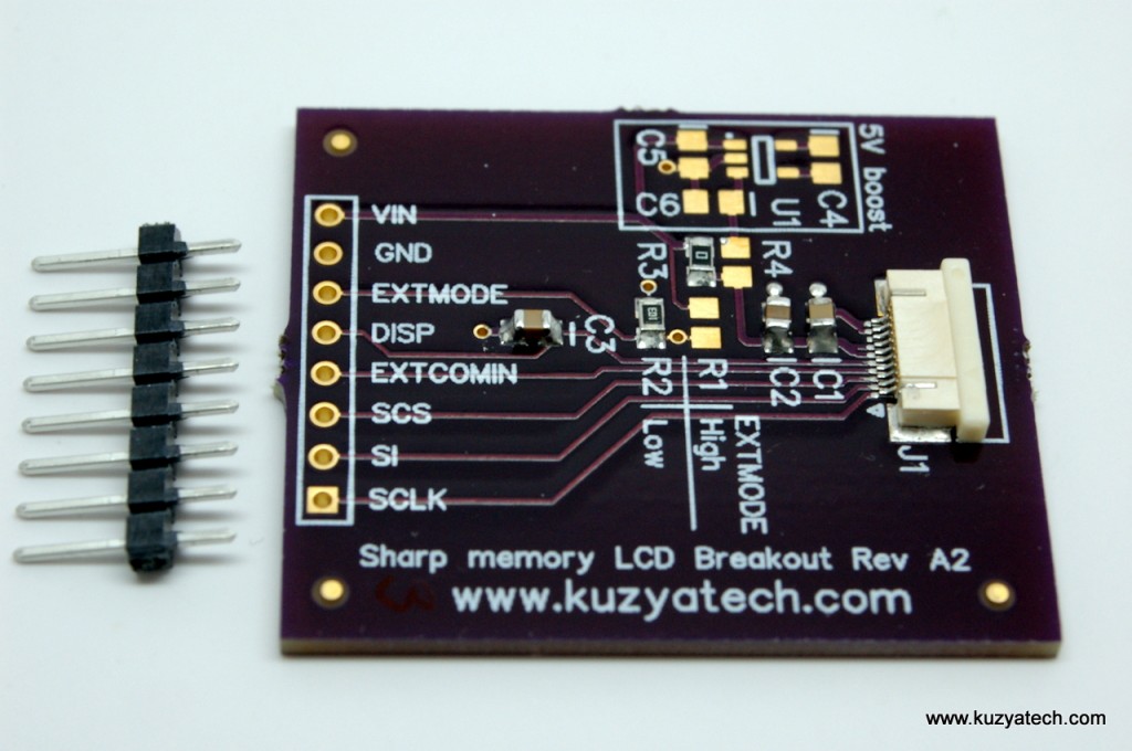
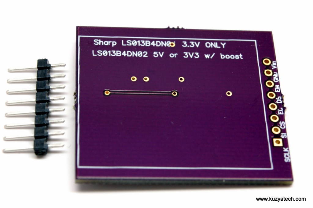
This is a simple breakout board for Sharp’s Memory LCD display family (LS013B4DN02, LS013B4DN04, LS013B7DH03, LS013B7DH06, LS027B7DH01 and LS044Q7DH01). Those are the parts known at the time of the writing, though more models are coming out all the time. So far Sharp’s been keeping very consistent interface and there is a fairly high chance the board will work with all of them. In a table below is a list of displays I am aware of on the US market. Models needing 5V boost are marked accordingly.
The board brings all pins to a 0.1″ header and provides necessary caps and resistors. Revision A2 adds an optional boost converter for those wanting to run 5V display from sub 3.3V supply which is needed on color version, 2.7″ and larger screens and also some of the older ones.The footprints are there, but parts are not populated to save cost on the base version. A version with boost is now also available. This is an open design under CC BY SA license.
Schematic is here for A2, or here for A1. The board was tested using craftycoders Arduino library. Sharp application notes are here and here.
Other (untested by me) libraries I am aware of are:
- A fork of the above library created by hybernaut with support for Leonardo and Arduino Micro boards https://github.com/hybernaut/SharpMemoryLcd
- Ti MSP 430 Launchpad library is at https://github.com/astuder/MSP430-sharp-LS013B4DN02-memory-display
- The smemlcd Raspberry Pi library https://github.com/wrobell/smemlcd by Artur Wroblewski provides C library (with Python 3 bindings) for Sharp Memory LCDs. At the moment only 2.7″ LCD screen (LS027B7DH01) is supported.
These boards are available from my Tindie store. You get an assembled board and a 0.1″ header separately, so that you can either solder it in or use the connector or wires of your choice.
If using the same library, Arduino pin connections are as follows:
| Breakout pin | Arduino pin | Breakout Pin | Arduino Pin |
| 1 SCLK | 13 | 6 EXTMODE | 4 |
| 2 SI | 11 | 7 GND | GND |
| 3 SCS | 12 | 8 VCC | 5V |
| 4 EXTCOMIN | 3 | ||
| 5 DISP | 2 |
For more informaton, see my previous posts: Sharp Memory LCD breakout- boards arrived and Testing Sharp LCD breakout board


I designed a very similar breakout board a while back.
My code for the MSP430 LaunchPad might be of interest to your non-Arduino readers/customers as it will probably work with your breakout boards.
https://github.com/astuder/MSP430-sharp-LS013B4DN02-memory-display
Thanks, added your link to my board description on Tindie
Is there a way to make one that can mount on the Launchpad board? So that it slides onto the existing header with the correct pinout?
Certainly, anything is possible 😉 What else would you envision being useful on such a boosterpack?
I’ve forked Craftycoder’s SharpMemoryLCD library and got it working with Leonardo and Arduino Micro: https://github.com/hybernaut/SharpMemoryLcd
I’m going to continue working on it so can specify the pins in your sketch vs. specified in the library. I found 2 other Sharp Memory LCD libraries on github but I like that this one extends the Adafruit GFX library.
That’s very cool. Another possible feature would be to support the new LS013B7DH03 version, that’s a higher resolution panel (128×128 vs 96×96)
Samples ordered from Mouser–thanks for the heads-up!
Post updated with links to all the great libraries for this display I’ve become aware of since the original date
Hi, I have purchased the LCD after getting inspired by watching your videos. Now, I am trying to write a character to the LCD which isn’t going well. The clear command is working with the display turning on but I am unable to write.Any help is appreciated. Here’s my code :
#include
int SCS=10;
int SI=11;
int SCLK=13;
int EXTCOMIN=4;
void setup()
{
pinMode(SCS,OUTPUT);
pinMode(EXTCOMIN,OUTPUT);
pinMode(SCLK,OUTPUT);
pinMode(SI,OUTPUT);
digitalWrite(SCS,HIGH);
tone(EXTCOMIN,40);
SPI.setClockDivider(SPI_CLOCK_DIV16);
SPI.setBitOrder(MSBFIRST);
SPI.setDataMode(SPI_MODE0);
SPI.begin();
SPI.transfer(0x20);
delay(3000);
}
void loop()
{
SPI.transfer(0x80);
delay(3000);
for (byte i=0; i<30;i++)
{
SPI.transfer(i+1);
delay(3000);
for(int j=0; j<50;j++)
{
SPI.transfer(0x0F);
delay(3000);
}
delay(3000);
SPI.transfer(0x00);
}
delay(3000);
SPI.transfer(0x00);
}
Can someone please explain why is EXTCOMM clamped to half VDD? Thank you.
Did you mean EXTMODE? It’s not, you populate one or the other resistor to set that pin high or low, but not both
I see that the schematic shows the components needed for the charge pump.
What size parts (caps) are needed?
Is there a BOM for the charge pump?
Thanks
Caps are all 0805 10V+, X5R or better
The chip is Linear Tech LTC1517CS5-5
You’d also have to move 0 Ohm jumper from R3 to R4
Hi would this work with the newer LS013B7DH06 ?
The pinout is the same, but you may need to either populate the 5V boost section or feed it 5V instead of 3.3V. Though some people had success with straight 3.3- depends on the screen.
That’s great thanks, I’ll give it a go 🙂
Hi
Are the break-out boards for the 4.4″ LS044Q7DH01 still available
Thanks
А где сам LCD берут ?