Today’s teardown subject has been waiting for its turn for a while- I picked it up at the last Design East conference in Boston in 2012. There, Microchip and Energizer were talking about low power design and using these Schick Hydro 5 power razors as an example. Hot on the heels of my repair of a Philips Sonicare toothbrush, this seems to be a good fit for a comparison. Both things do essentially the same thing- they shake, light up some LEDs and not much else.
Product unpacking
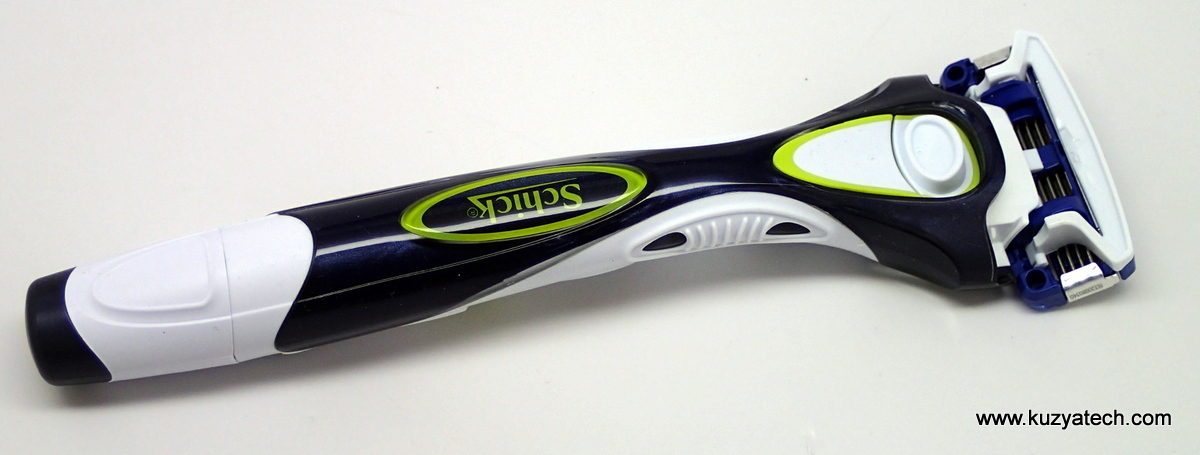
Schick Hydro 5
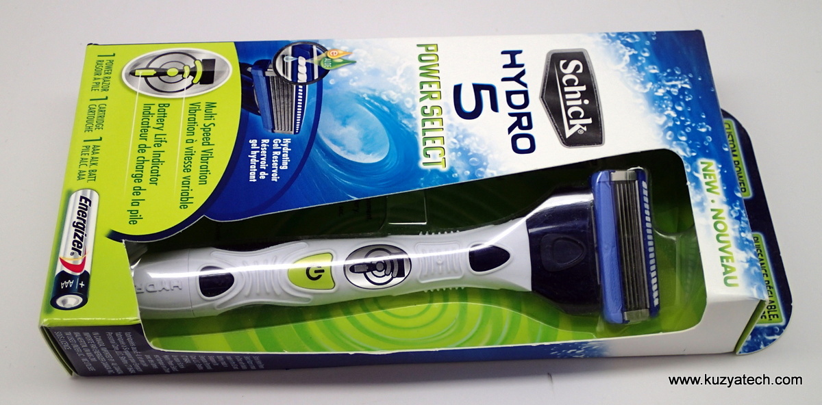
Retail packaging-top
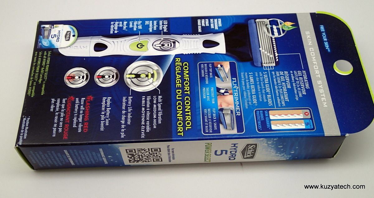
Retail packaging-bottom
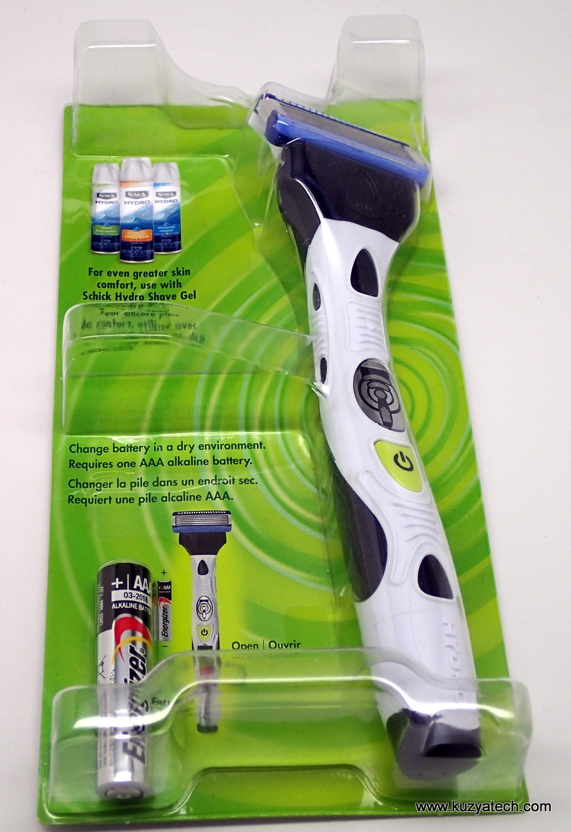
Impossible to open blister pack
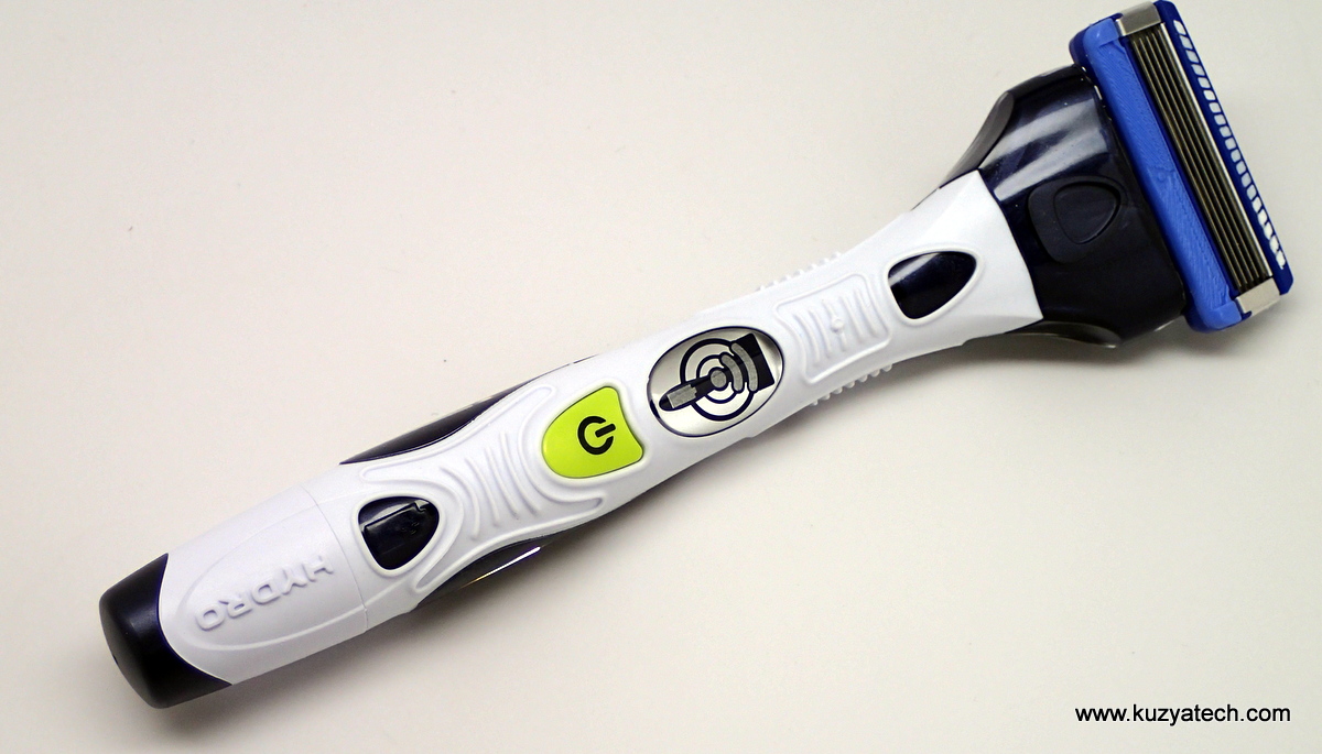
Fairly attractive design, with soft overmold. The battery compartment cap is on the lower left
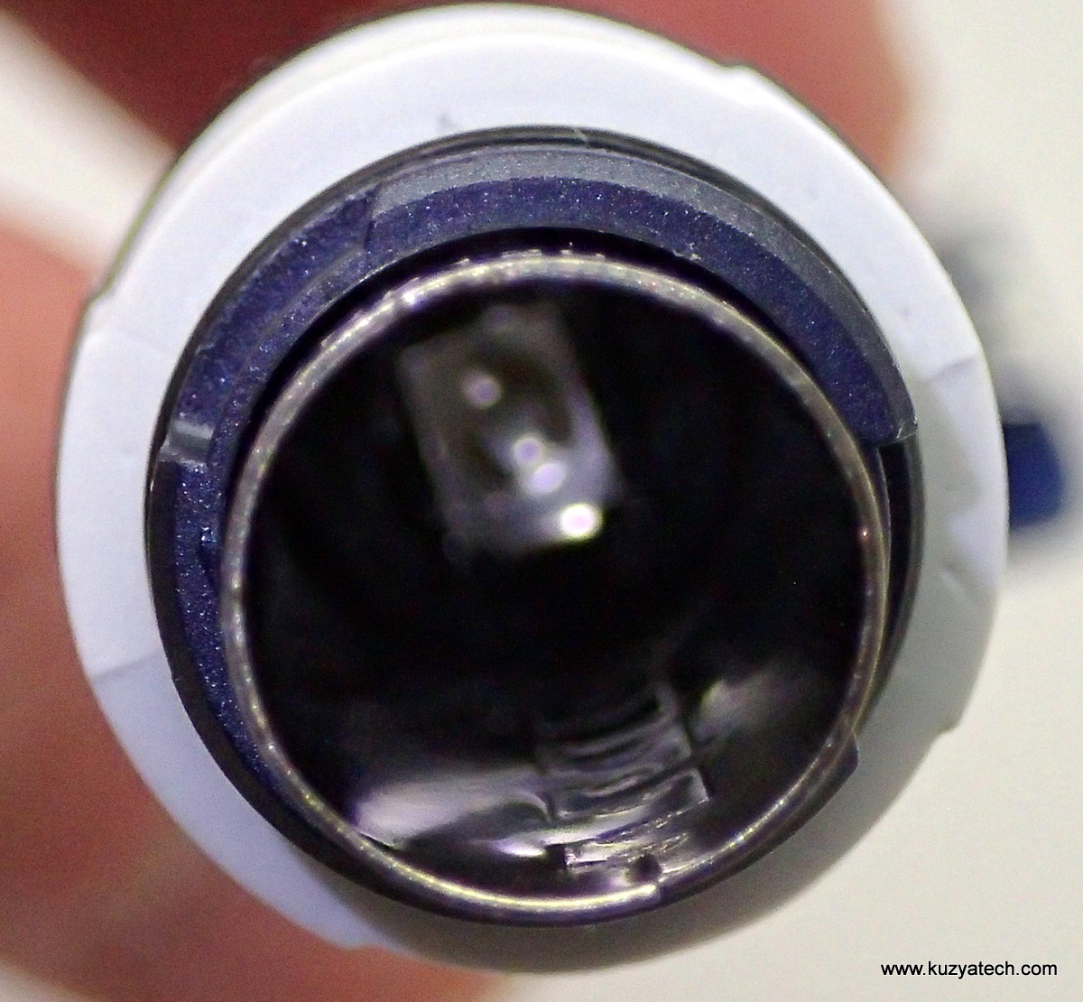
Metal insert -battery compartment
Teardown
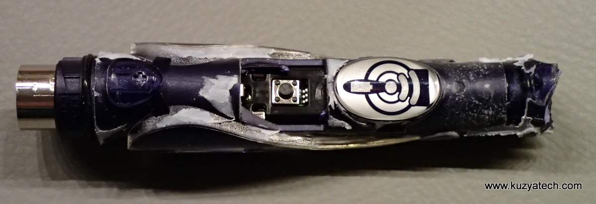
“Built like a tank”.
It took some serious effort to take the razor apart. It appears to be overmolded and not designed to be opened ever, so cutting and breaking was required. The case feels very solid and well designed. To get the electronics out required pulling the metal battery compartment sleeve out. That dragged the board with it as well.
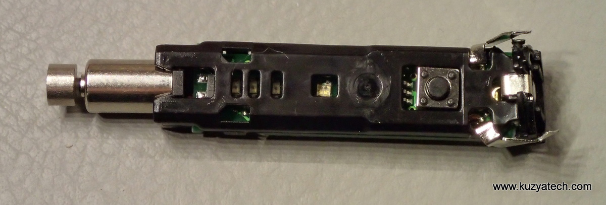
Board assembly- we can already see the vibration motor on the left and the LEDs an a button.
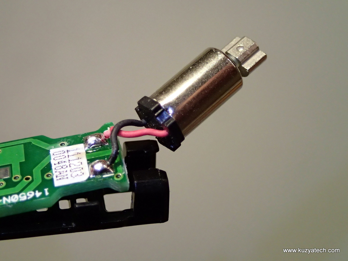
More details on vibration motor
Design
And finally we can see what we came for- the control board
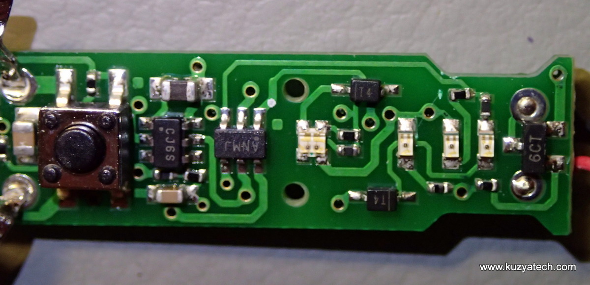
Top side of the board
We have a bit of a headstart in figuring out what’s what here- the razor came with a handy little flyer form Microchip, listing the parts used:
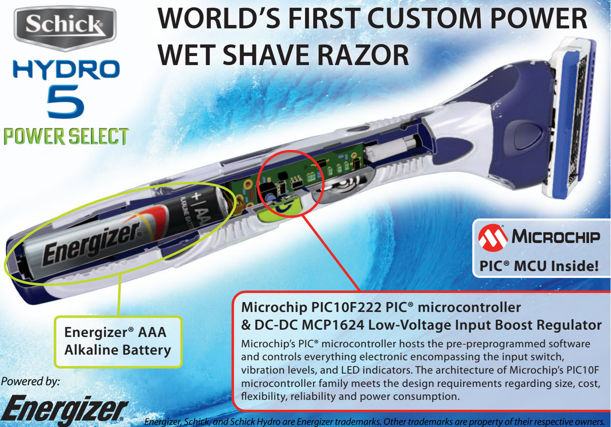
Handout from the Design East Microchip session
So we know the main Micro is a PIC10F222 in a 6 pin SOT23 package (marked ANMJ) and the power supply is an MCP1624 (Marked CJ6S). The two diodes marked T4 are typically 1N4148 and the SOT23 part next to the motor appears to be a 0.5A 45V NPN transistor from NXP (BC817-40). Curiously enough, the latest PIC10F222 datasheet does not list AN as a possible marking.
Now let us trace the connections on the board. Luckily with only two layers it’s not a huge task:

Schematic and waveforms
The design is somewhat predictable- we have a 3V boost power supply feeding the PIC microcontroller. The motor is powered directly from the battery voltage and is controlled via an NPN transistor. Speed is adjusted by varying duty cycle of the PWM signal (It goes in steps of 40%, 60% and 97%). It gets a bit more interesting with the LED multiplexing. The razor uses 4 green and 1 red LEDs, but PIC10 here only has 3 pins available for all of them. The most obvious optimization was done by grouping things together- lower LED is always on with the motor- might as well drive them at once. The red/green signal (Waveform 3) is more involved- to drive red the microcontroller switches to open drain mode and only pulls down, generating pulses between Vbat and 0 V. Since the same pin is also used as an ADC input, the battery voltage could be sampled at that stage. To drive green on, the output is driven high and then switched to an input (or Hi-Z state), so that lower voltage ends up somewhere between battery voltage and supply voltage. LEDs for the second and third speed segments are driven similarly (Waveform 2). To turn both on, a normal full swing pulse is needed, but for LED2 only mode the line gets driven high and then switched to input. In both cases additional signal diodes are added to intentionally raise activation voltage for the LED in series.
Looking at the back of the board, there is not much there with the exception of the ICSP pads, which may be handy if you are inclined to try reprogramming the thing. I’ve labeled them to the best of my knowledge.
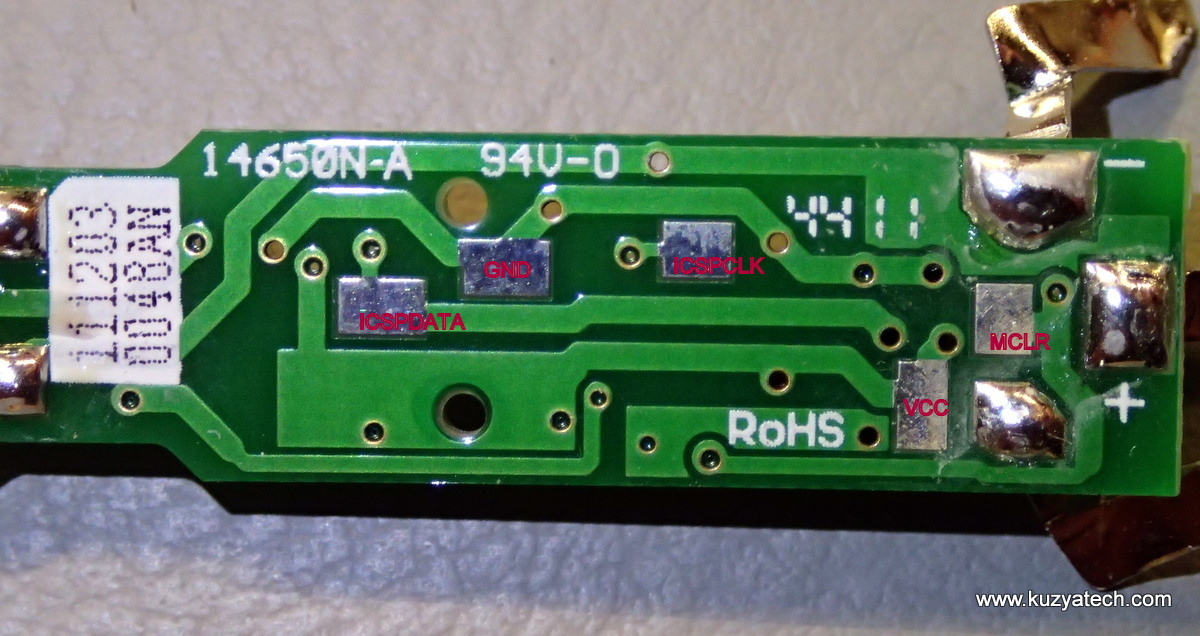
Back side of the board- test points
Power consumption numbers:
- Idle, no LEDs on 60-78uA
- Low speed on: 35mA
- Medium speed: 50mA
- High speed: 69mA
I have not been able to observe any deeper sleep modes even after leaving the razor idle for a while. The timer may be set to longer interval or there may not be one. At 70uA , and with an average AAA battery supplying about 1Ah, that’s almost 1.5 years of sitting on the shelf doing nothing. Of course by that time, there will be no capacity left to actually run.If we only look at runtime, we get between 29 hours at low speed and 15 hrs at high speed before new batteries are needed.
Resources:
- Microchip PIC10F222
- Microchip MCP1624
- NXP BC817
-
EEVblog discussion thread with some interesting insights
Pingback: Schick Hydro 5 razor teardown « adafruit industries blog
Did you try reading the contents of the PIC’s Program Memory? I’d like to know if there is code protection on this consumer products.
No I did not. Maybe when I get a chance I’ll try