
Today we have a somewhat vintage teardown. Even though you can still buy this Watchdog BWD-HWA Water Alarm in home stores and online, the design itself probably goes quite a few decades back as we’ll see below. We’ll also learn a few things about low power design. Rumor has it these last forever on a nine volt battery!
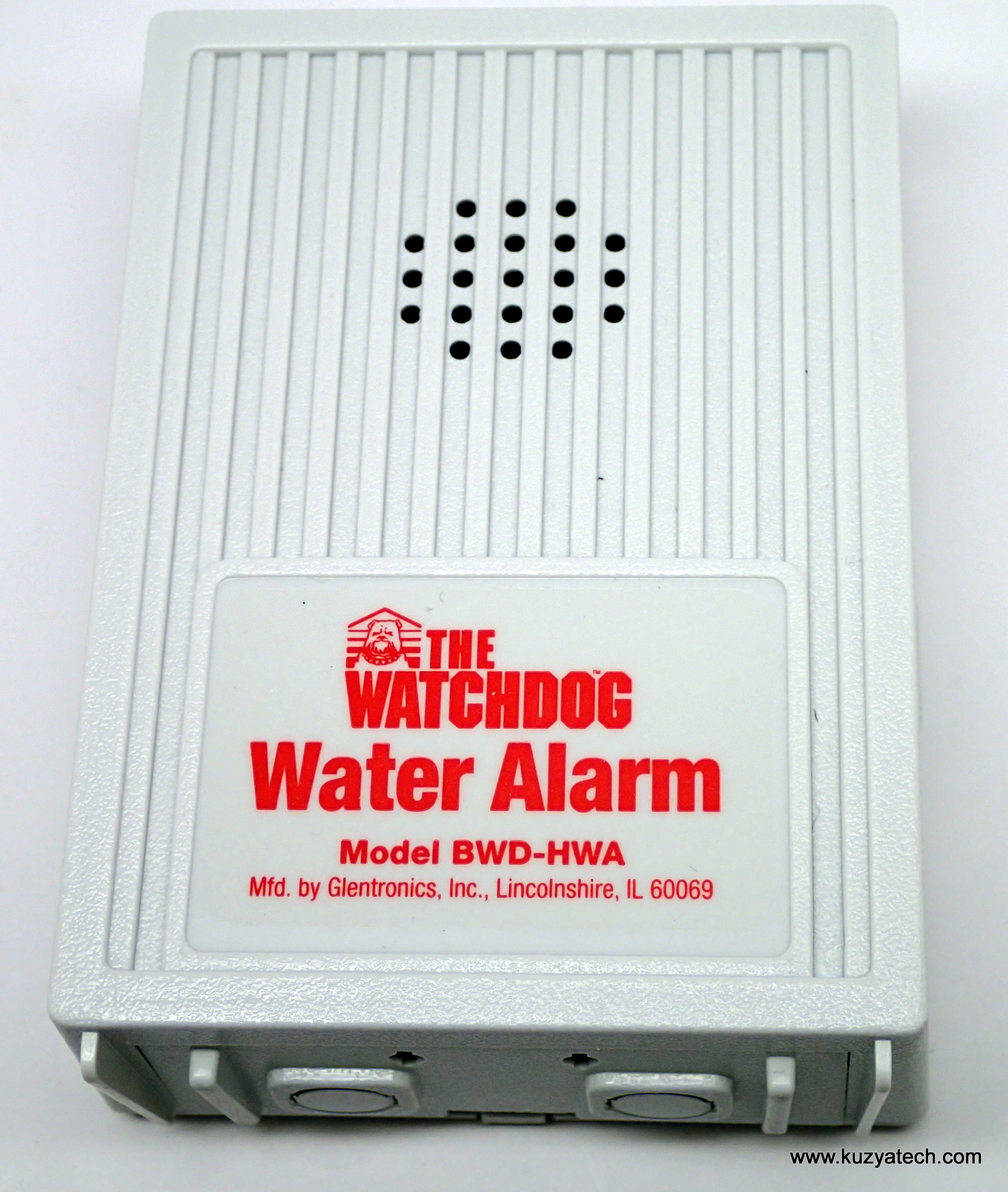
Front view
Introduction
This alarm has a pretty simple task- sit somewhere quietly and watch for water leak. As soon as its two bottom contacts touch water, it goes BEEEP loudly. If it’s not handy to let the thing sit on the floor, you can also mount it higher using the slot on the back
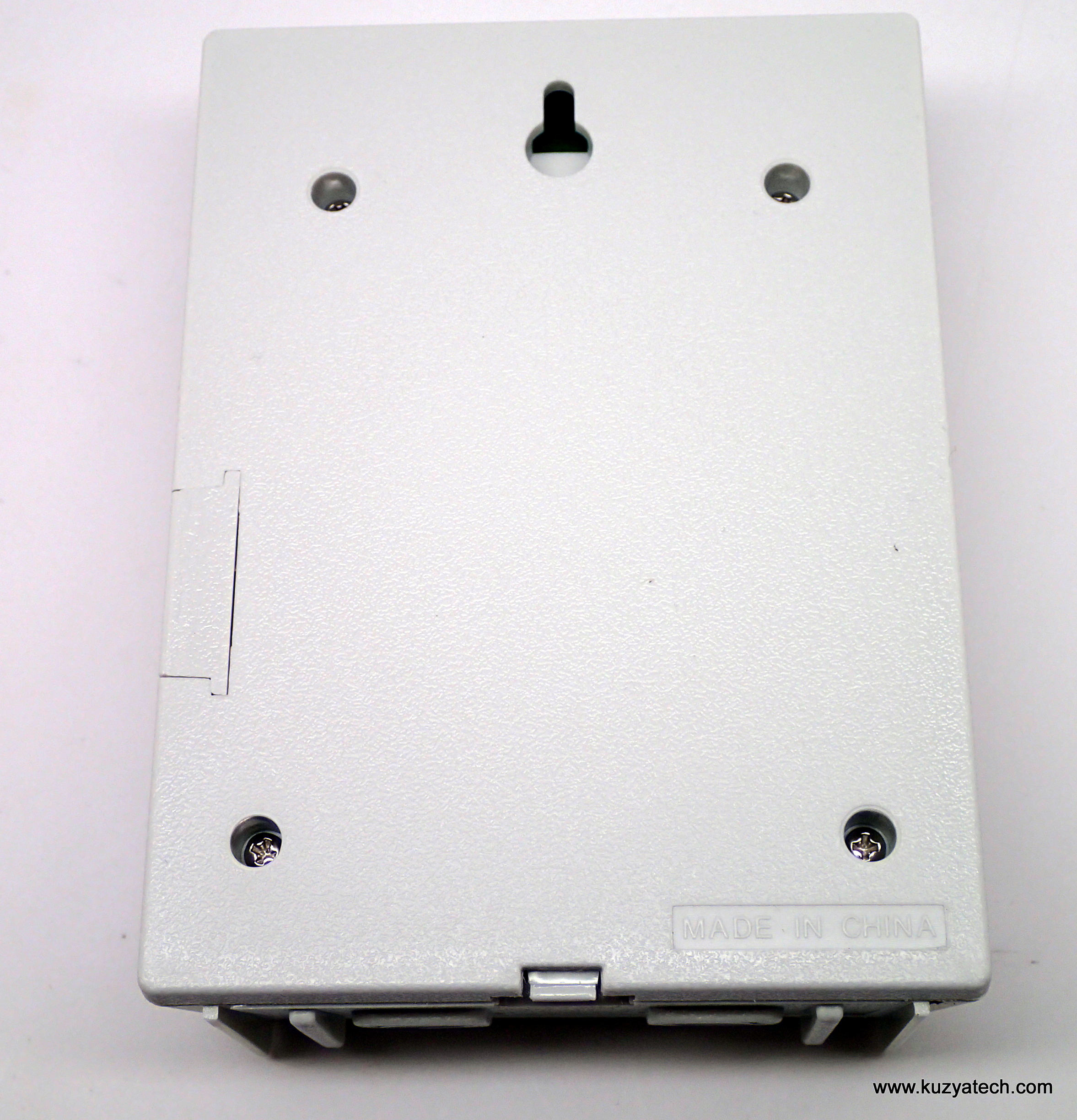
Wall mounting slot
and run the sensors down using the coiled wire:
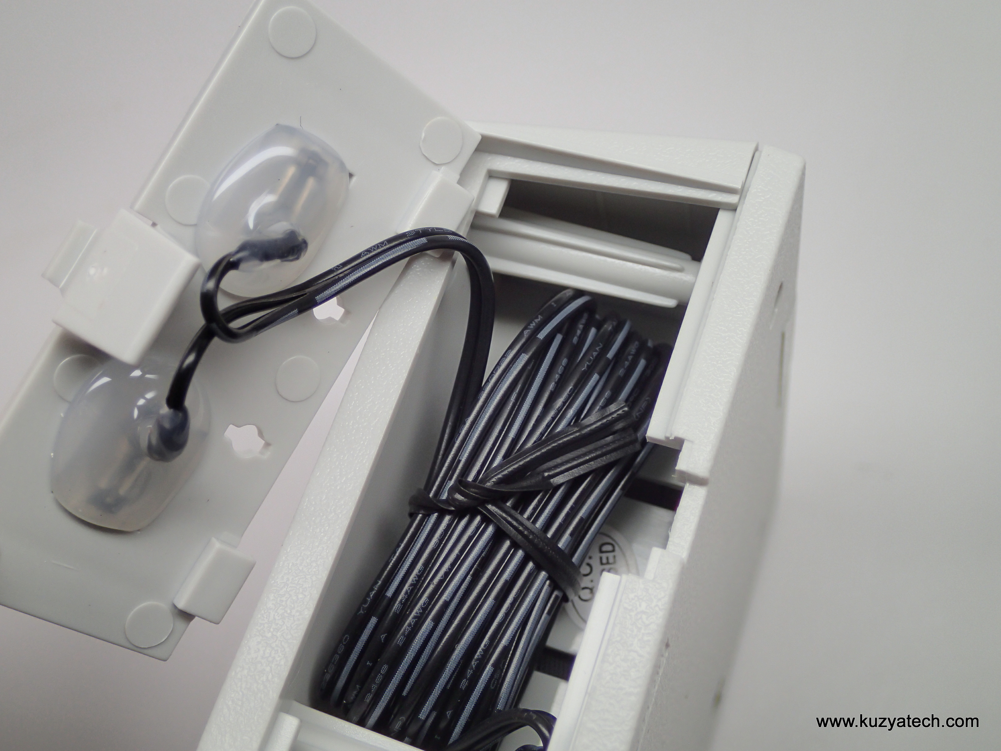
The sensors could be local, or remote using supplied wire
Let’s take the cover off:
The design is nicely compartmentalized, with separate areas for sensor wiring, battery and electronics. Note strain relief loop around the plastic post. If installed properly with sensor facing down, there is a good inch or so of clearance before water on the floor shorts the battery- good touch.
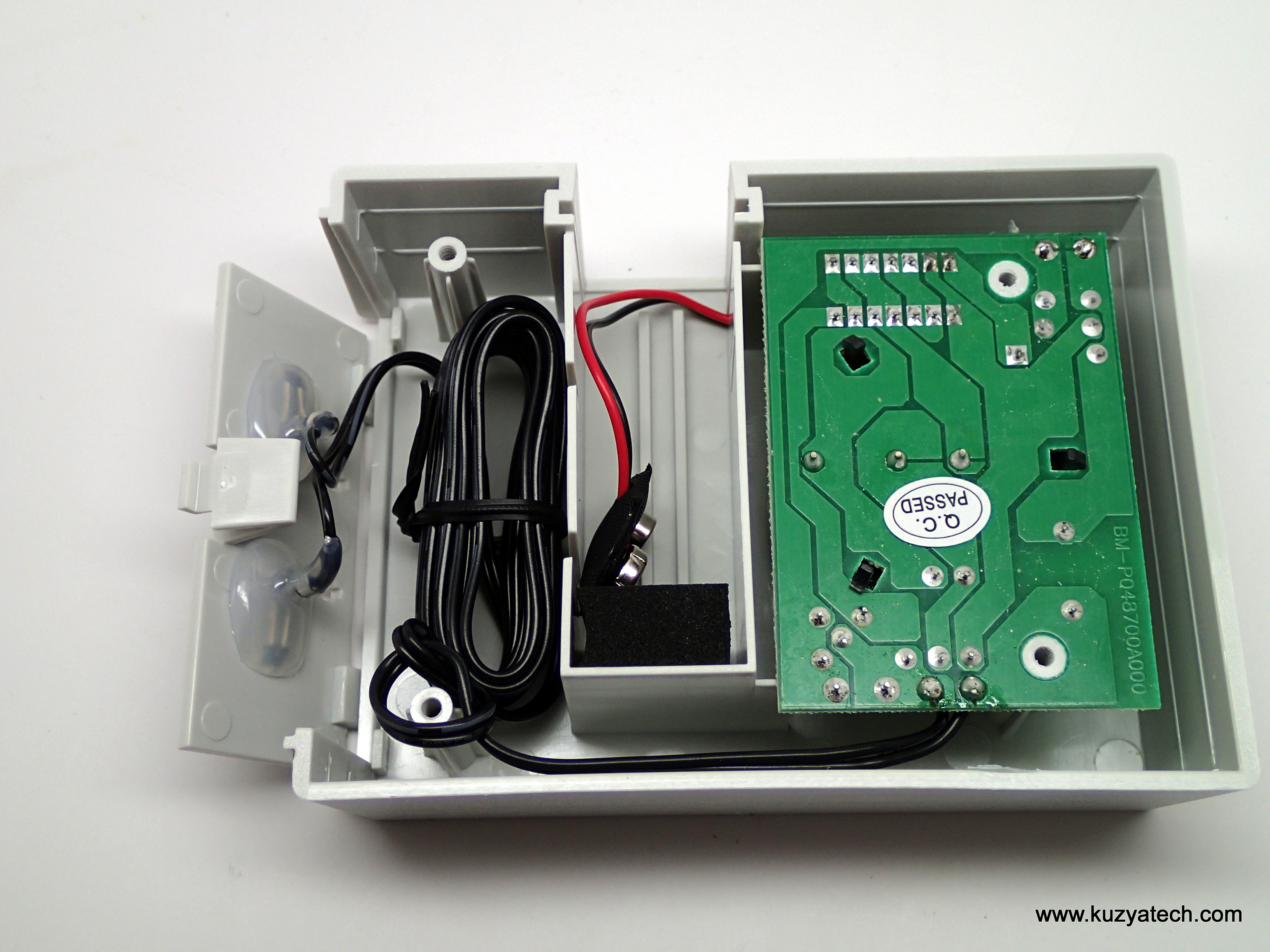
Rear cover off
The electronics:
Not much in here and sure looks like the eighties! A single sided FR-4 board, one CD4069 (CMOS Hex Inverter), 2N7000 NMOS FET and a few jellybeans is all it takes to drive a very loud buzzer. The bare board is made on week 17 of 2015.
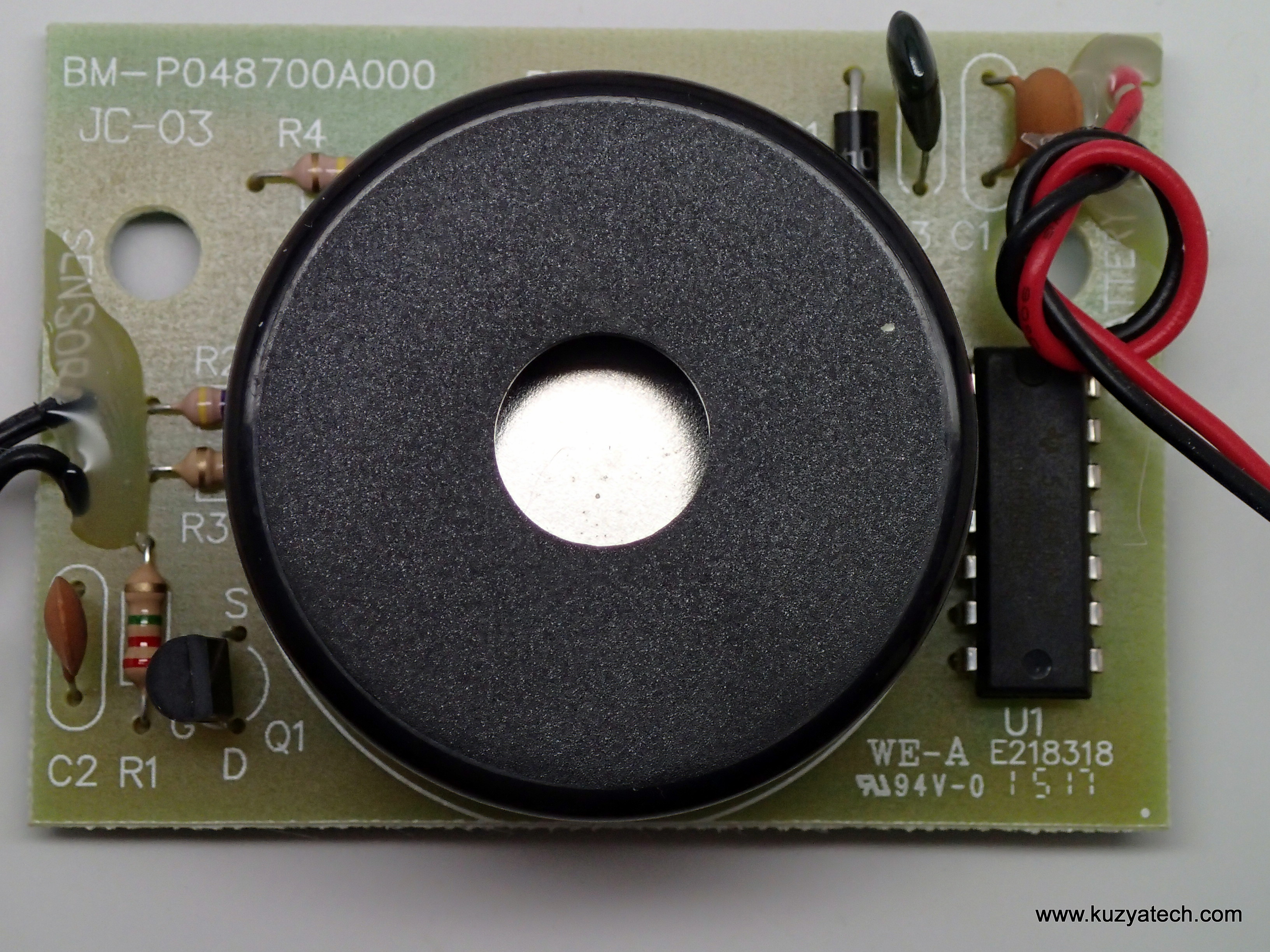
Board top
Soldering job looks decent. It looks like many of the CD4069 gates are in parallel
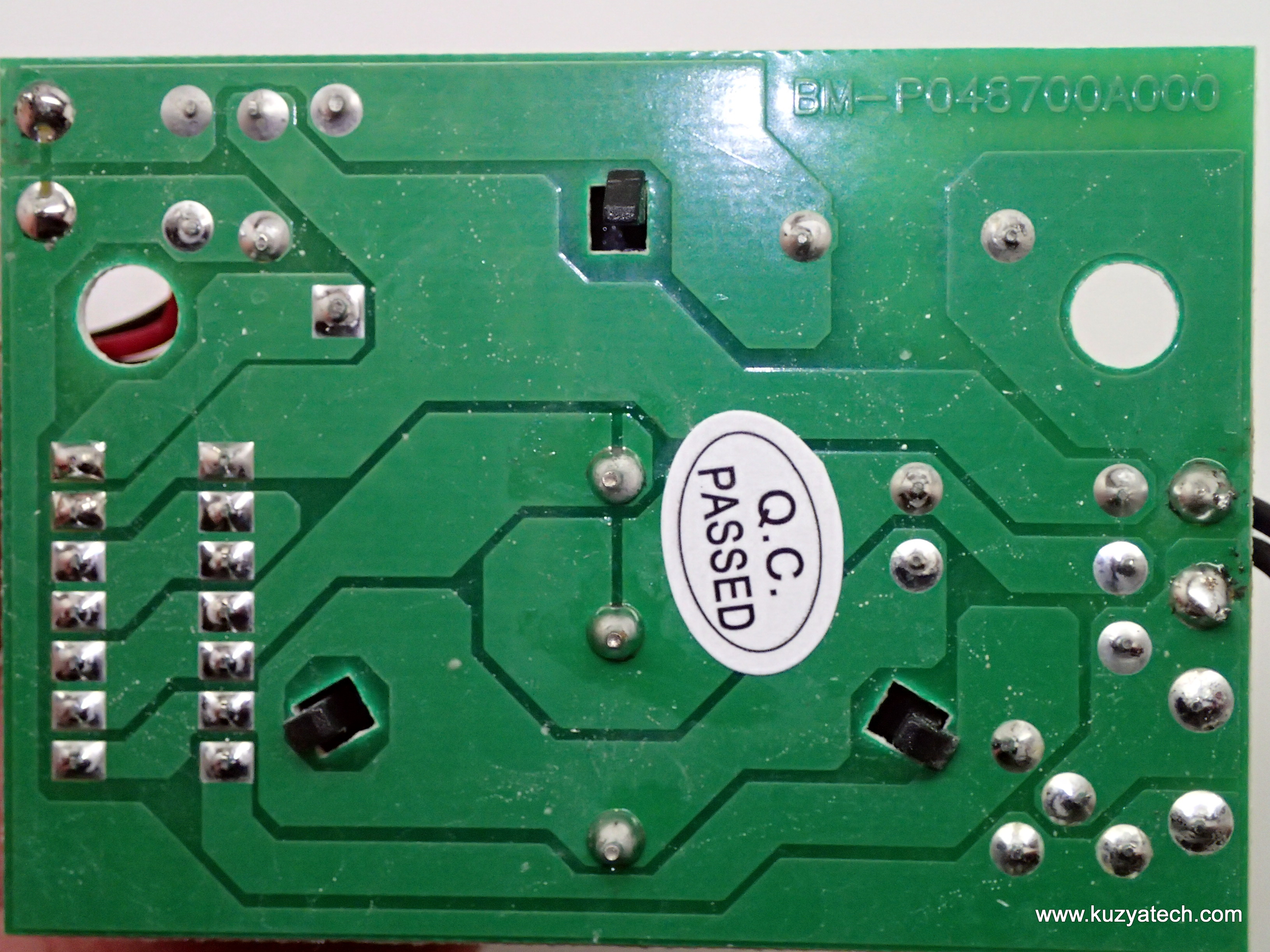
Board back- all throughole.
Another strain relief on the battery wires to go over case plastic.Nice attention to details. CD4069 is so old, the datasheet is still from Harris. The part runs from 3 to 18V, allowing direct operation from the 9V battery.
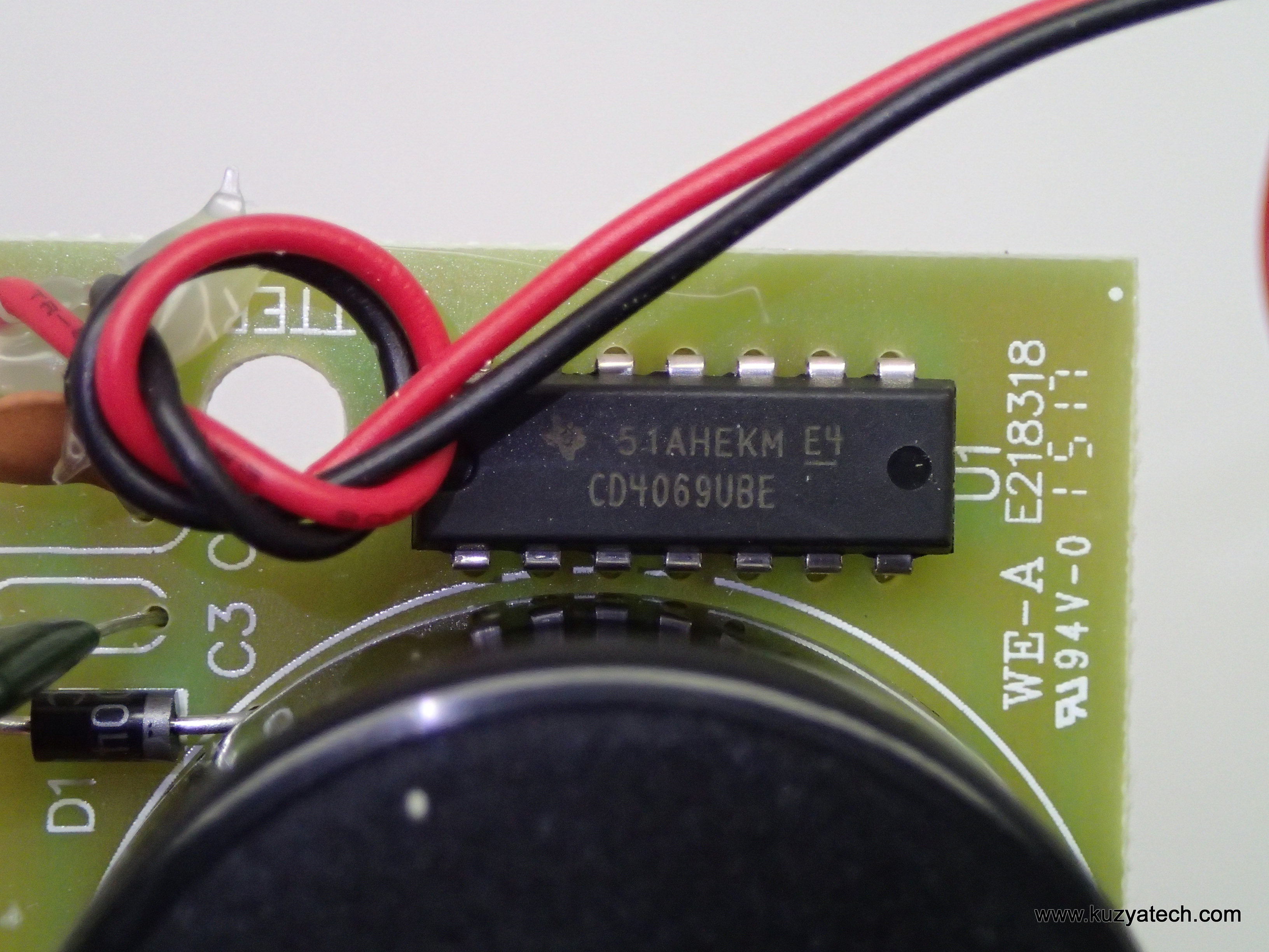
CD4069UBE details
Can you find something wrong in the picture below?

2N7000, but what’s up with the silk?
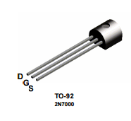
It appears Source and Drain are swapped in silk. As a quick check in a Fairchild datasheet shows, Source should be on the left. (It also happens to be where the ground trace connects.) Oh well, at least the part itself is connected correctly.
Standby power consumption test:
Powering the unit from a power supply and trying to measure standby current proved “interesting”. None of my meters could resolve it even when in uA range. Turning to my trusty uCurrent from EEVBlog, i discovered that the number is around 2-3nA! No wonder these things last forever on a battery.
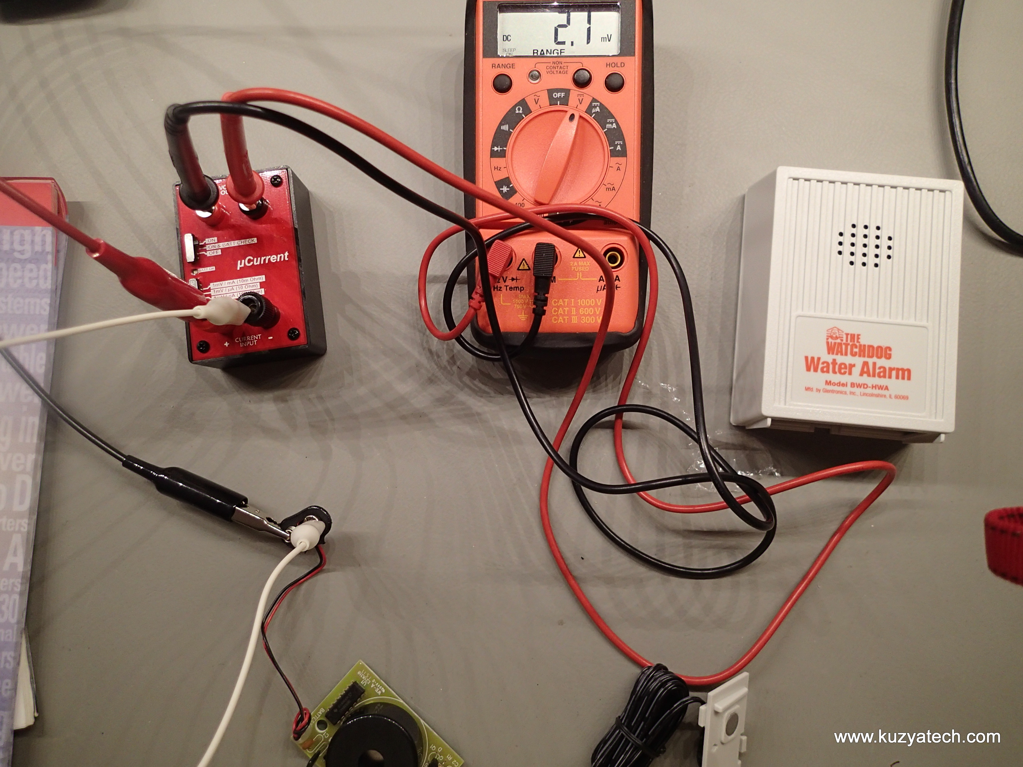
Measuring current. the uCurrent is set t 1mV per nA
Schematic
And now on to the schematic. Luckily it does not take much to make one on a design this simple. I drew the chip U1 as seven parts for clarity: the power pins and the six inverters. What we have here is two essentially independent sections. The top one detects water and turns the power on. Since there is no hysteresis, the alarm will shut off the moment contacts stop touching water. The bottom one is just a driver for the buzzer. Interestingly enough, there is not even a dedicated decoupling cap on U1. It just shares C1 with the rest of the board. So, we have: D1 (1N4004) for reverse battery protection and Q1 to control power to U1. With sufficiently conductive fluid touching the two electrodes, the gate of Q1 gets pulled up and it turns on. Q1 along with the forward drop of D1 determine minimum voltage the circuits operates at- around 4V, well beyond a typical 9V battery end of life.
While in standby, the only power drain is the leakage through C1 and Q1. I’ve tested it briefly by heating the board a bit and the current went up as expected. But at room temperature and at least on this unit it was in nA. The spec for 2N7000 lists 1uA as a max leakage with no gate voltage. So that’s the worst case idle figure. When alarm is on, the current jumps to around 11mA. With a typical 600mAh 9V battery, that’s good for a few days of beeping before the owner hopefully notices it.
The buzzer driver uses the six inverters to create an oscillator with a frequency of around 3.3kHz. Interestingly enough, each stage is doubled – I am guessing for better current supplying capacity at the outputs.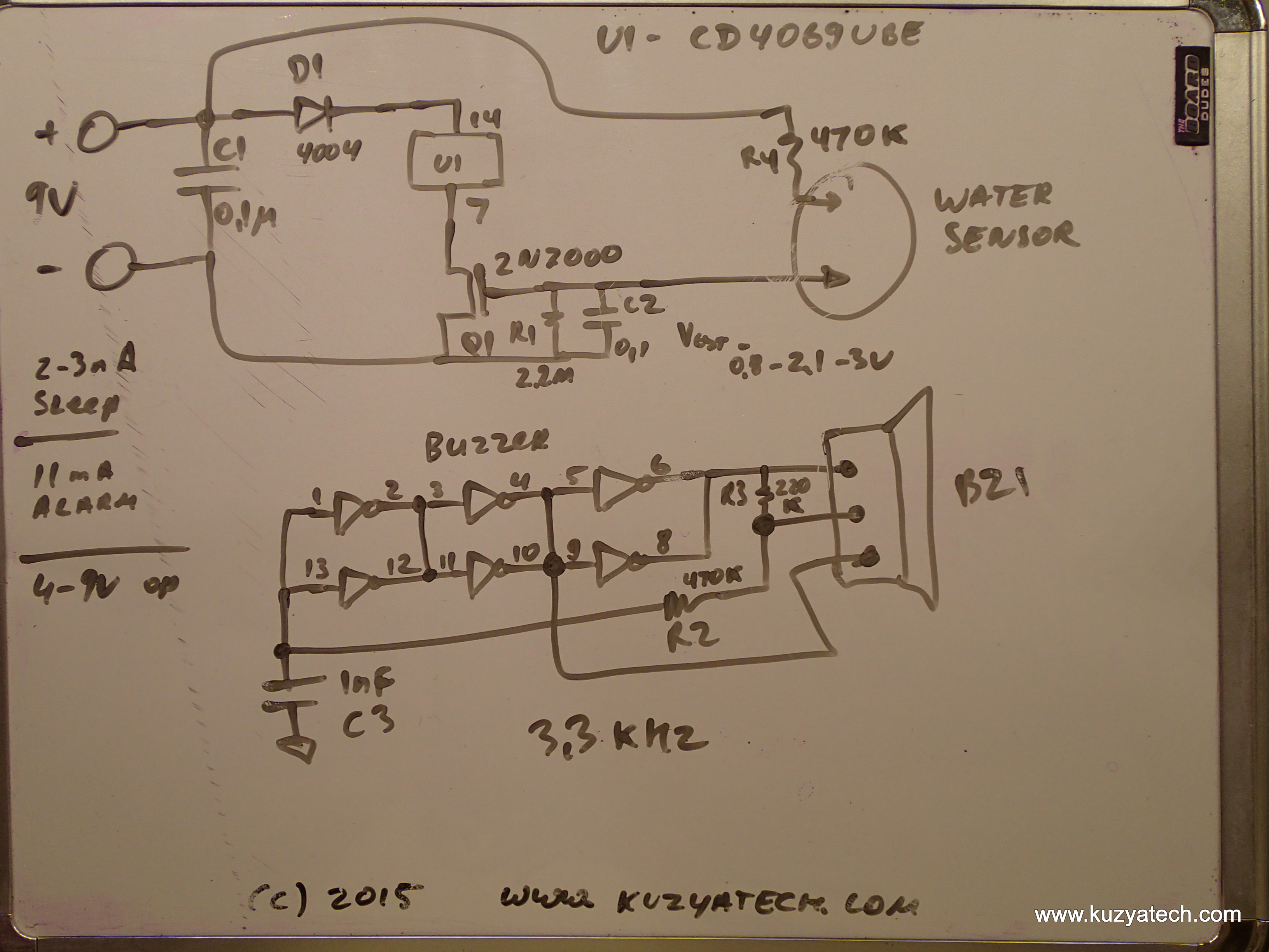
Conclusion
The design is simple and pretty clever with essentially no battery drain until triggered. I am a bit apprehensive about Q1’s gate going directly into the outside world with only a cap across- I’d prefer a series element or a clamp. There is no battery low indicator, but at such a low drain it will take years for the battery to need replacement. (Selfdischarge will probably be the main driver of that). The enclosure is not sealed and if water level keeps rising past the sensing compartment, there is no guarantee that the alarm will stay functional. Enterprising user may find it pretty easy to make an IOT version of this device- simply hand a 9V tolerant WiFi module on and make it send things out when alarm power turns on.
Very nice tear down and very in depth. Its great you even were able to build the schematic from it. First time I have seen the uCurrent being used as well. I need to get one of those.
where in this circuit is there voltage during no alarm but during alarm it loses voltage? Trying to use a 2n7000 mosfet to trigger an alarm panel
Looking to do the same. Replaced battery with power from my alarm system BU battery. Just need to figure out how to provide a dry contact
Can anyone tell me what R1 and C2 are for?
R1 keeps gate of the FET pulled low, to keep it off. and C2 is for some ESd protection as well as a bit of time constant
OK. Thanks.
I think I’ve figured it out. R1 insures the gate is held low until there’s enough voltage from R4 to turn the gate high. C2, I guess, is to even out any voltage spikes when the gate changes state?
Could the frequency of the sound be changed to lets say 1kHz ?
Is it dependent on the BZ1 and/or an RC ?
TR
I’m a little confused, looking at the BZ1 it has 2 leads yet the schematic shows 3 connections ?
TR
My mistake – I found the third lead.
TR
I’m considering trying to use one of mine as the switch for an aquarium pump to move the water that sometimes comes into my basement. (We have a finished room in quadrant I, a floor drain in quadrant II, and a sump in quadrant IV. The rainwater comes into quadrant III, and reaches the finished room before it gets to the drain or the sump.)
Has anyone here tried using this water alarm as more than just an alarm?
Thanks for the teardown. I’m planning to add a wifi module to add it to my home automation so that it can send me text message and turn off my Watercop valve.
Do you have any info on the buzzer, such as a part number? I’m curious about why it needs 3 leads.
Thanks,
Kevin