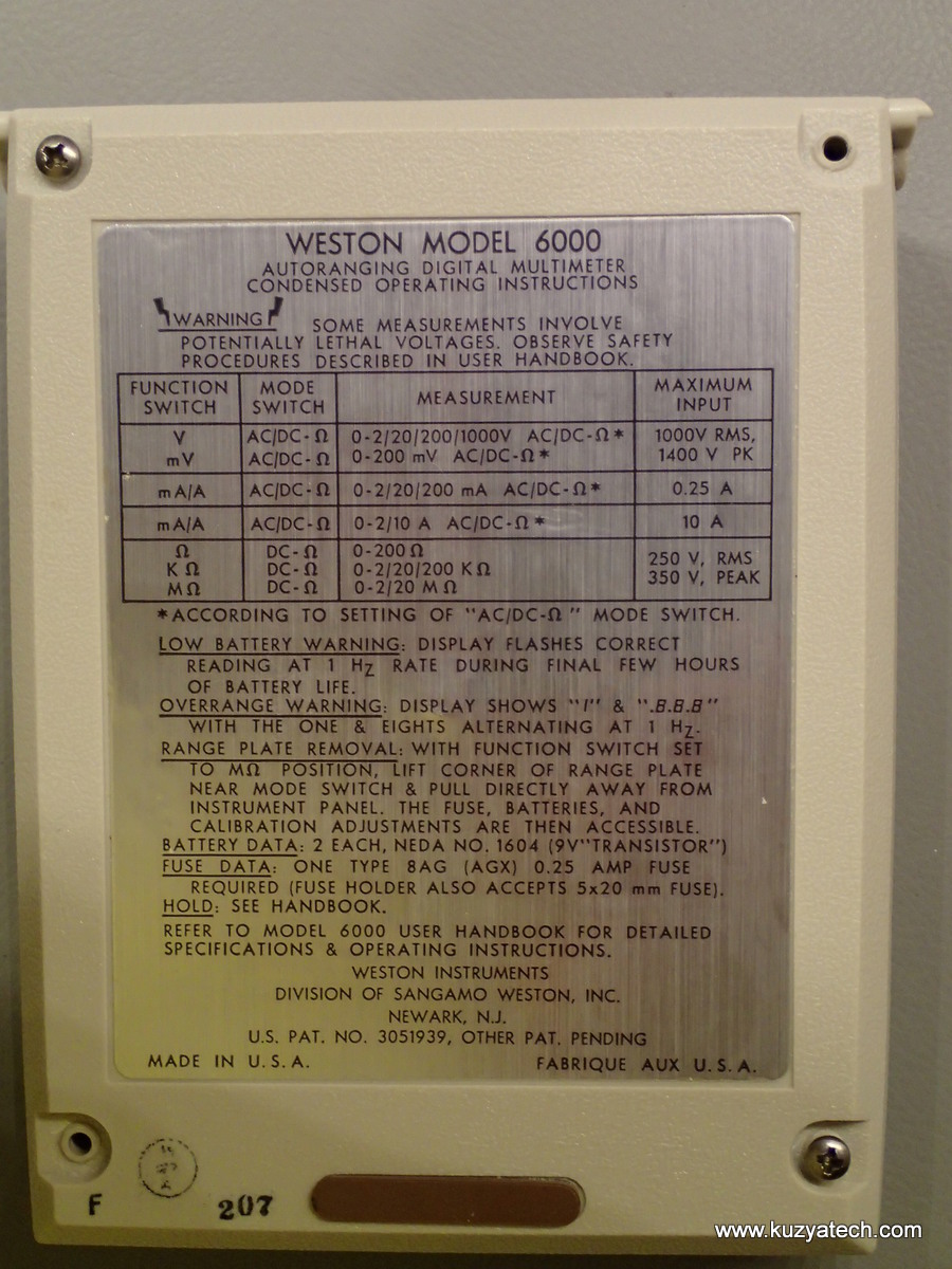
Another addition to my growing collection of vintage multimeters is this Weston Schlumberger Model 6000 meter from the mid 1970s
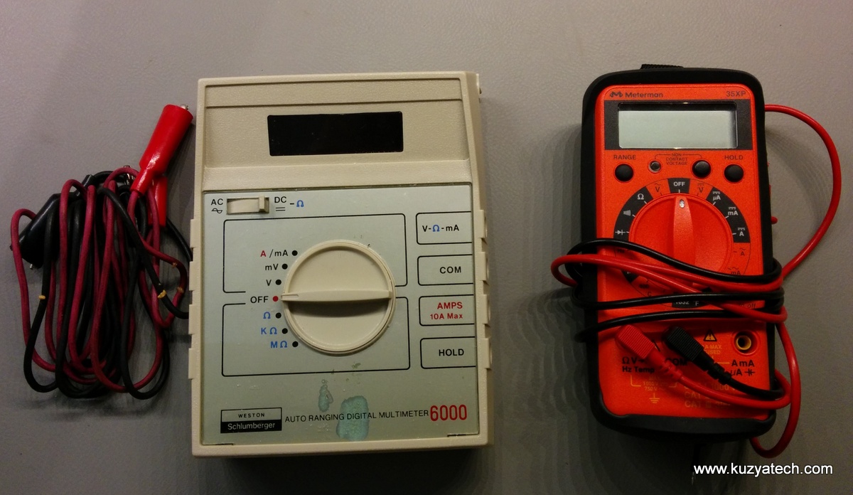
Old vs new(ish)- notice how square it is
The meter was listed as in almost like new condition except for a spot on the front panel. It came with (very rubbery) test leads and an actual printed user manual- a rare thing these days.The Ebay posting was worded very carefully to never mention whether the thing actually works, so I figured it did not really matter. If it does not- teardown turns into repair attempt and either way we learn something new.
Introduction:
The meter arrived and did indeed look very clean and lightly used. I turned it on but display remained dark. So let’s check the batteries first. Wait, how do we get to them?? Looking through the user manual, apparently you have to pop the front bezel starting near the AC/DC switch. Oh, this thing takes two 9V batteries:
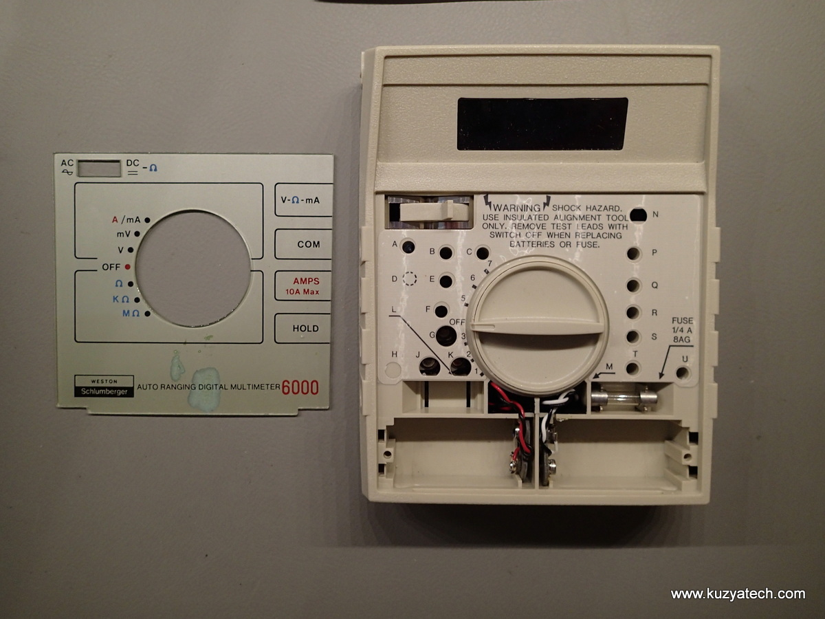
Front bezel popped out
This also explains the weird stain on the bezel- that’s where the batteries live and leak. There is also a large number of adjustment/calibration pots accessible through alphabetically named openings- a bit unusual! The user manual goes into great details on how to calibrate each range by supplying suiatble signal and then turning corresponding adjustments until the display matches the input. Overall not a bad design, batteries and fuse holder are easily accessible.
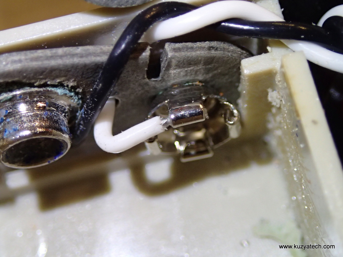
Cardboard battery connector. Note the crimped wire
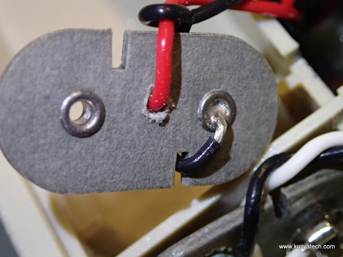 After cleaning the contacts and installing the two batteries, I turned the meter back on. The display stayed dark. Oh well, time to take’er apart!
Teardown
The back is held by four very nice stainless steel screws:
As seems to be the rules at the time, the manual is always included!
Back cover off:
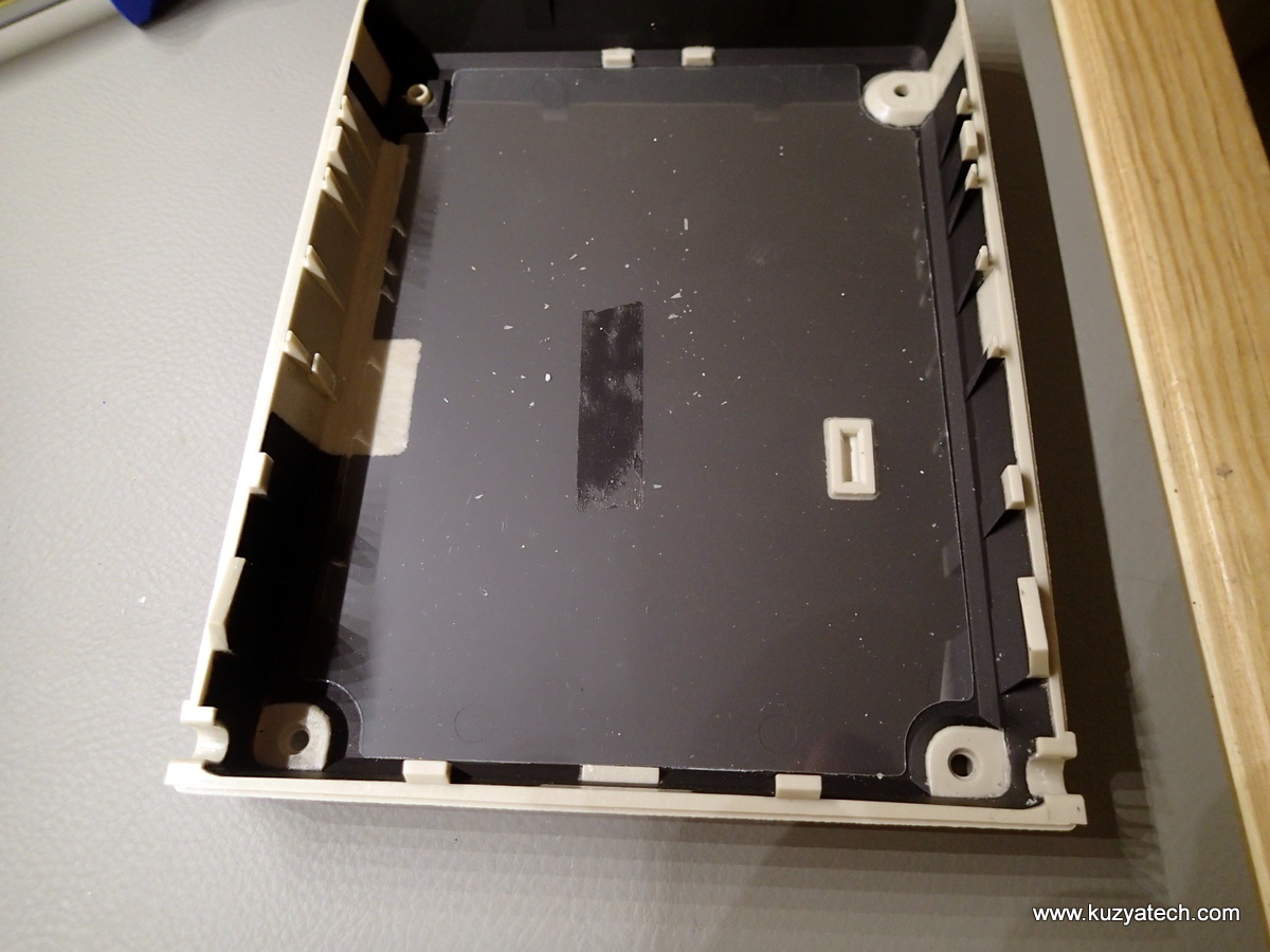
Spray-on conductive coating, about 3-4 kOhms across
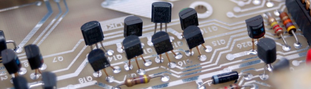
And now we come upon a work of art. For the admirers of ancient tracework, here is a high-res version.
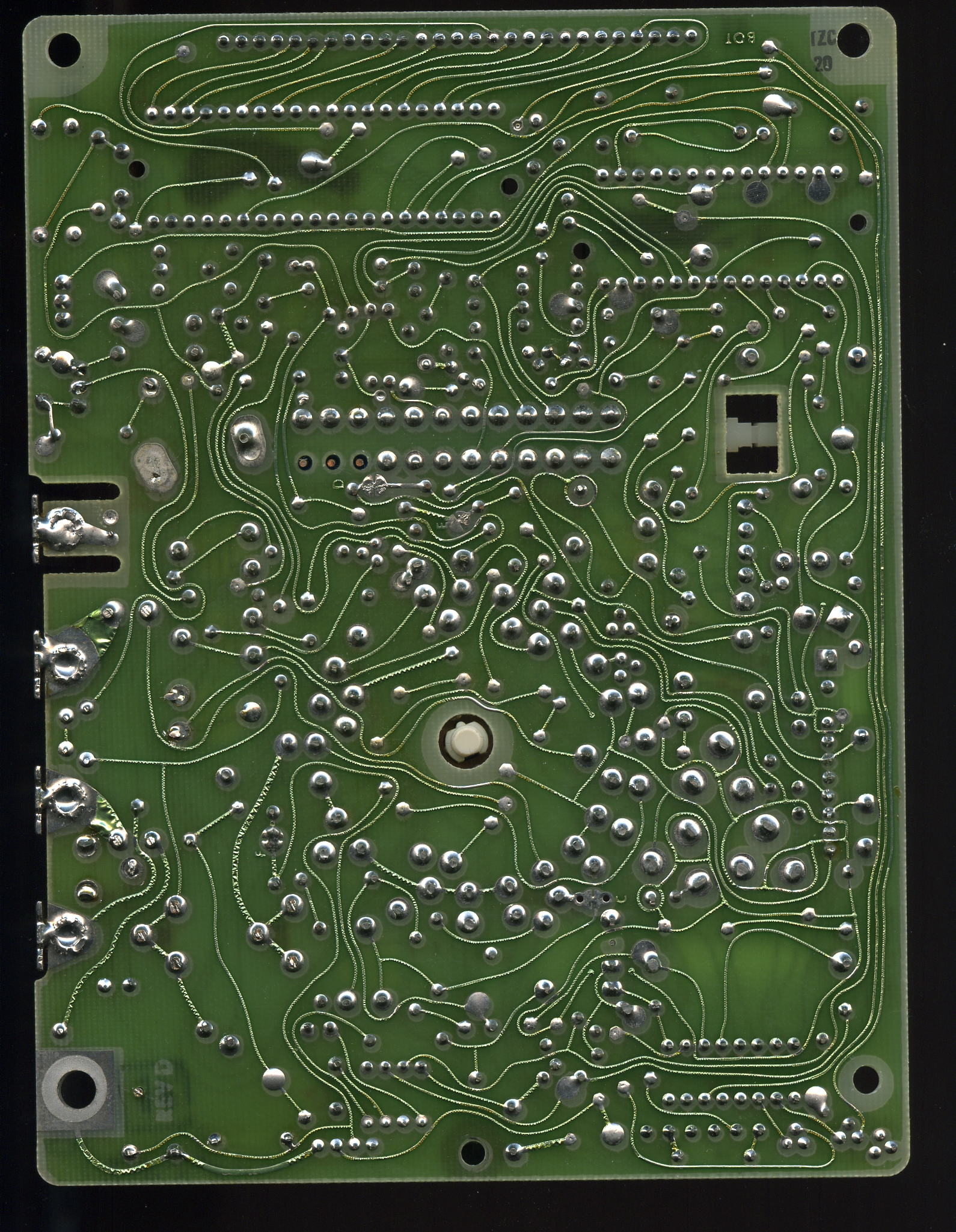
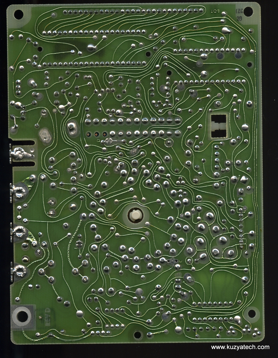
Hand drawn traces?
To remove the front, a range selector knob has to come off. Per MrModemHead‘s suggestion, a thick rag and a pair of locking pliers was all that it took:

Knob off. Interesting spring/clicking mechanism
There appears to be two “clicking” options here- one relying on the notches around the knob shaft, the other- around the outside. All selected by inserting the spring leaf and a brass roller into the appropriate spot.
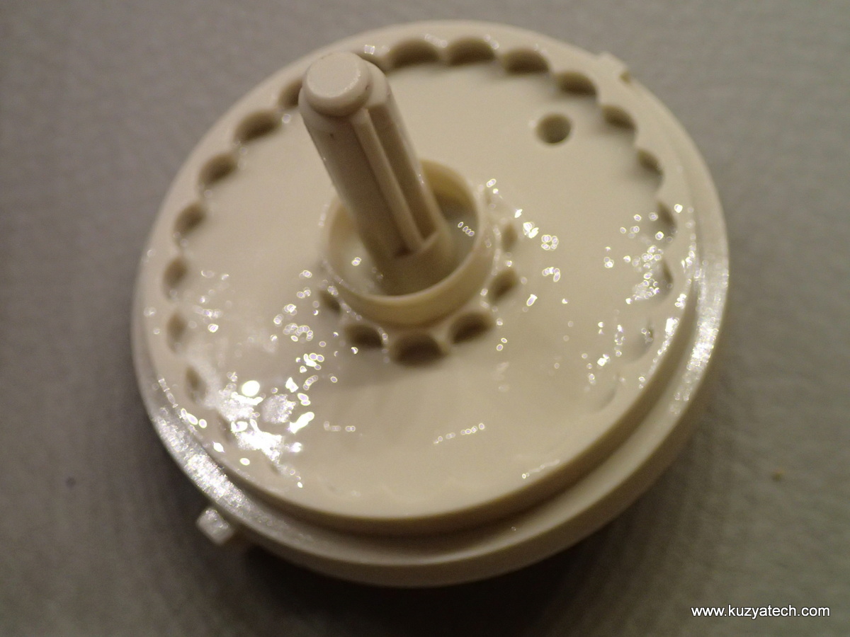
30 years old and still well lubricated
Now it’s only the fuse holding things up:
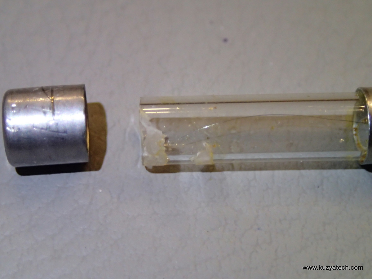
Woops, some things don’t like being touched
LCD display mount- no Zebra strips here
LCD strips
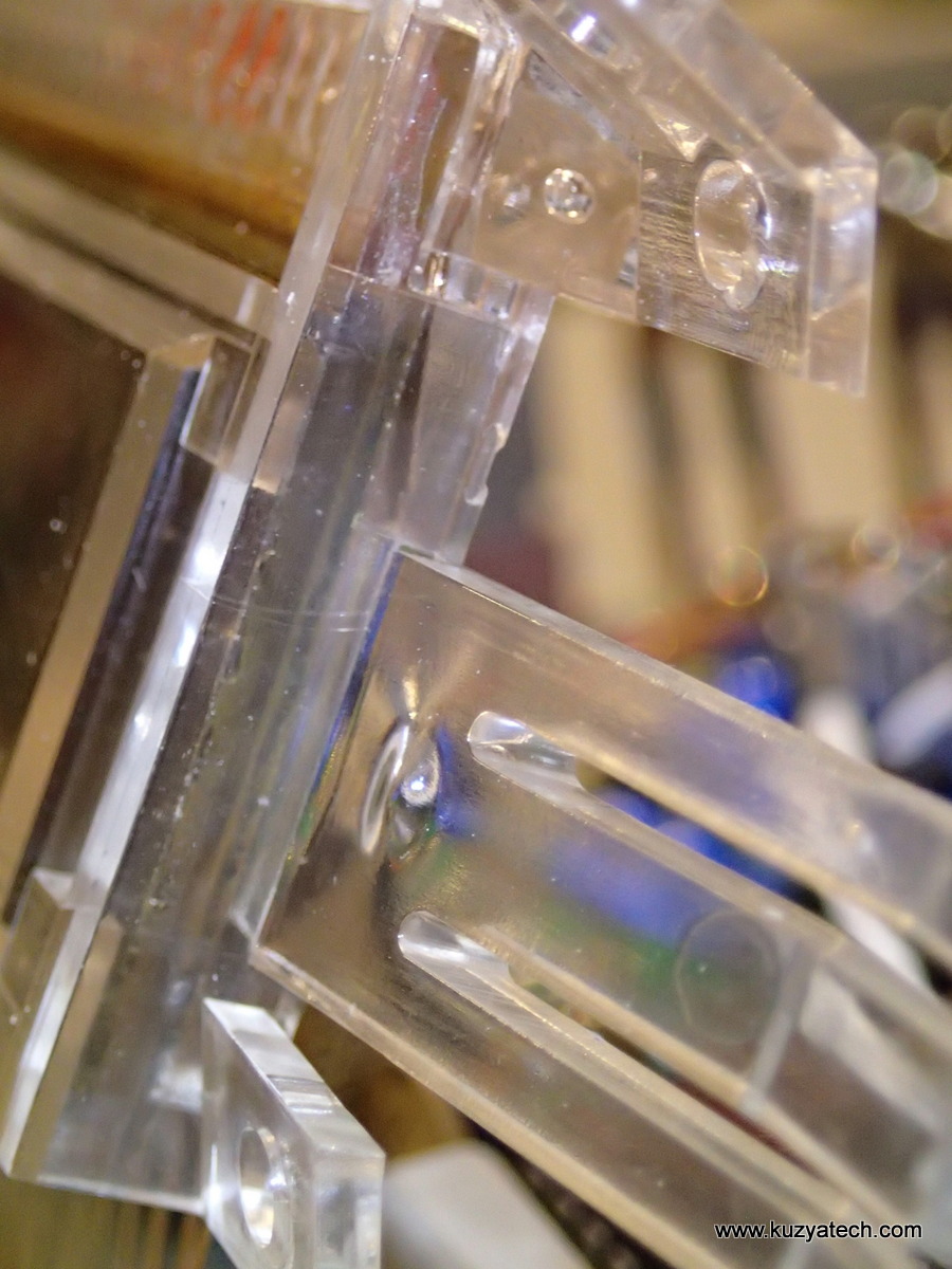
Display is help by a plastic piece, wedged between case halves
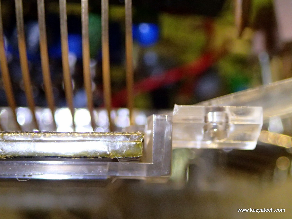
It’s an ooold LCD glass
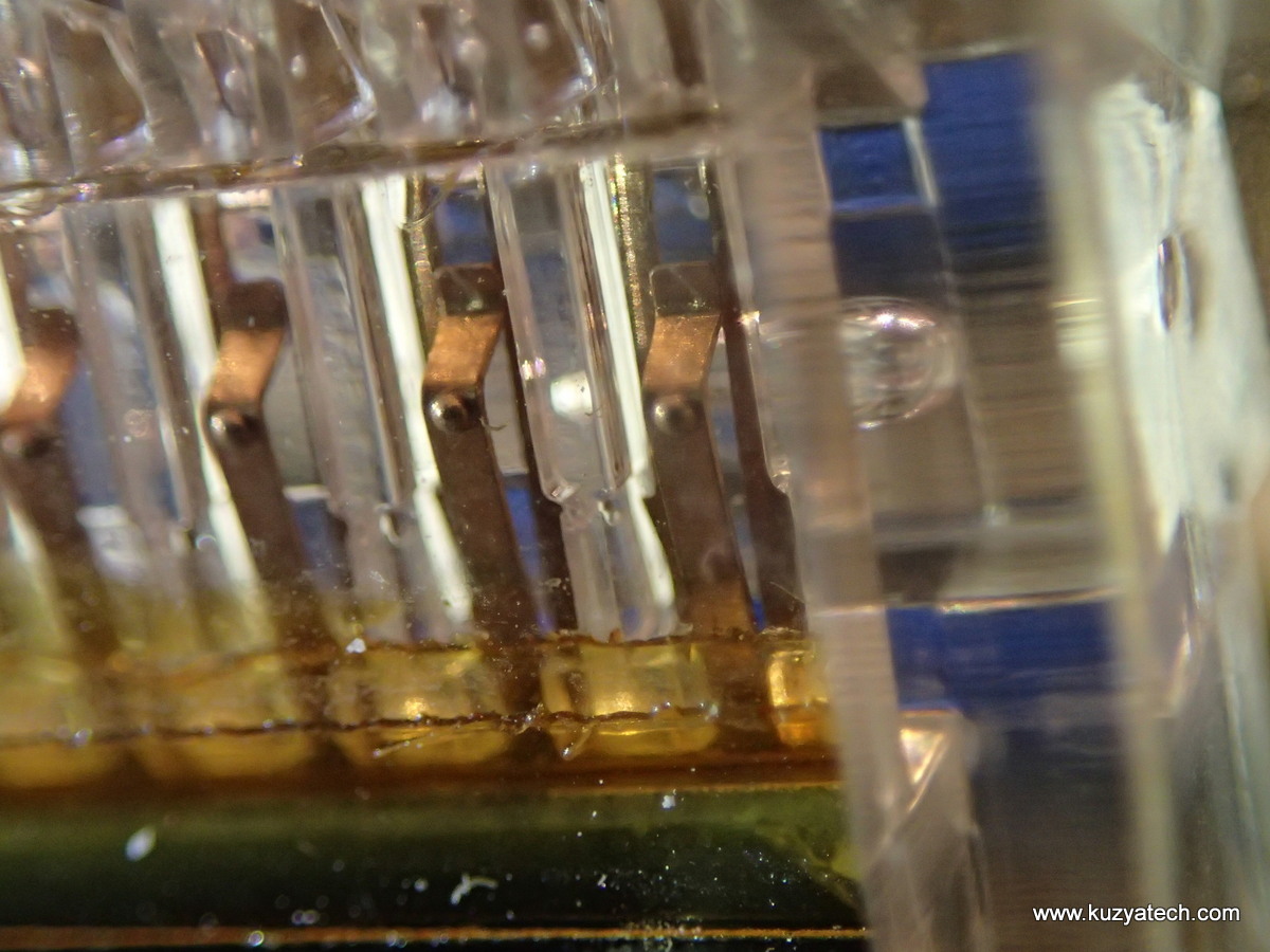
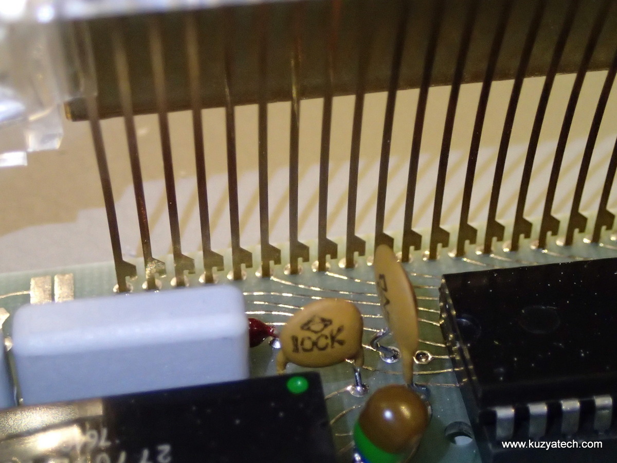
Springy contacts directly touching conductive traces on the glass
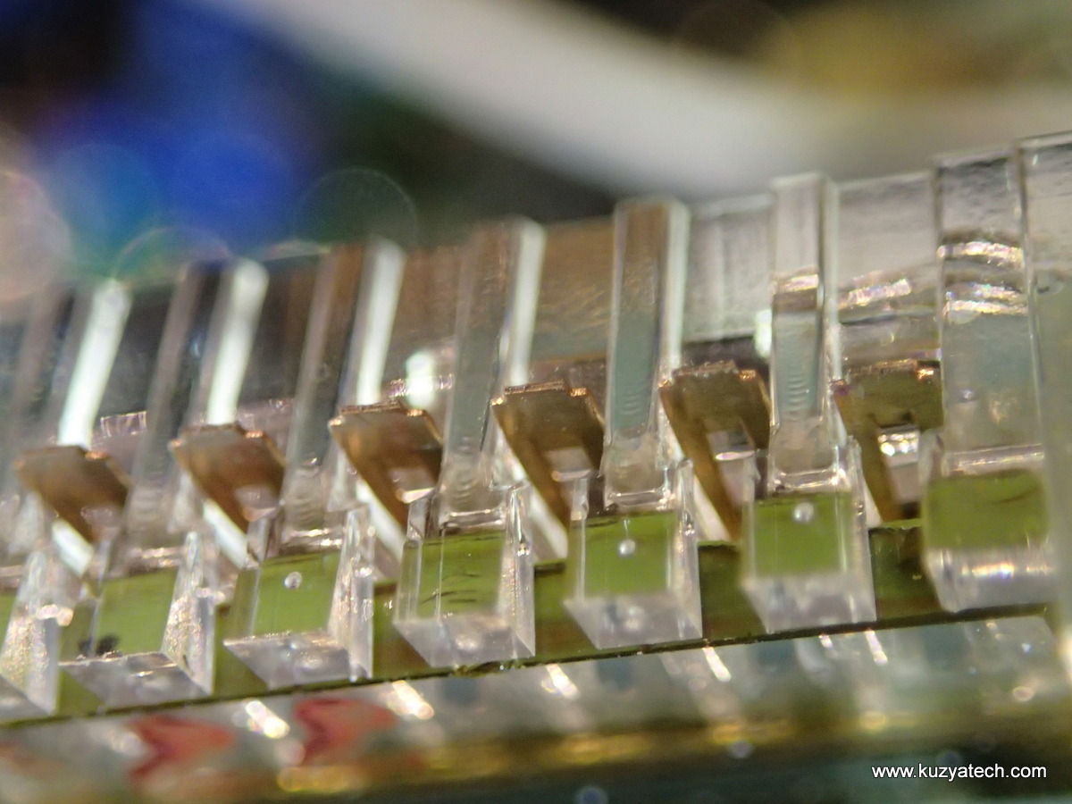
There does not appear to be a way to remove the screen without first desoldering the strips on the bottom

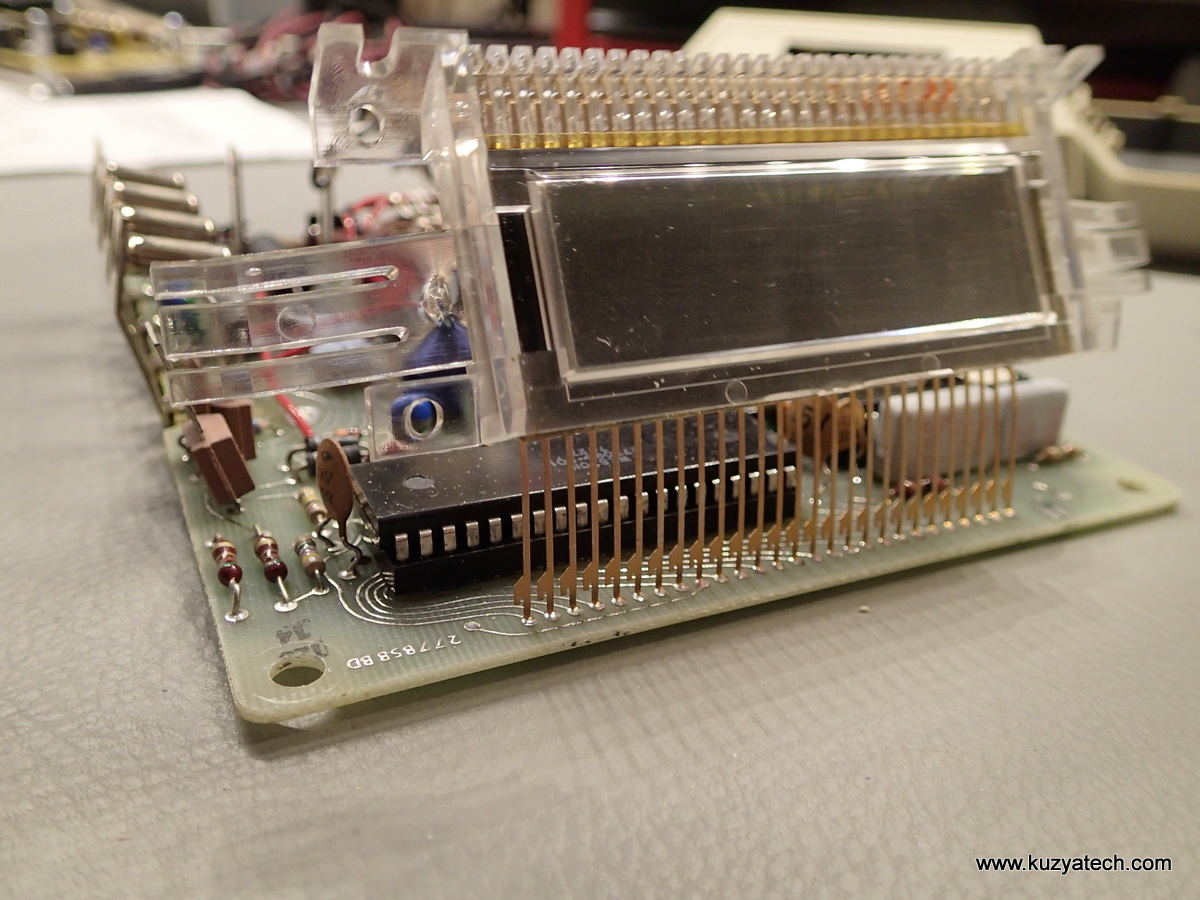
Side terminals view
Back view

Top view
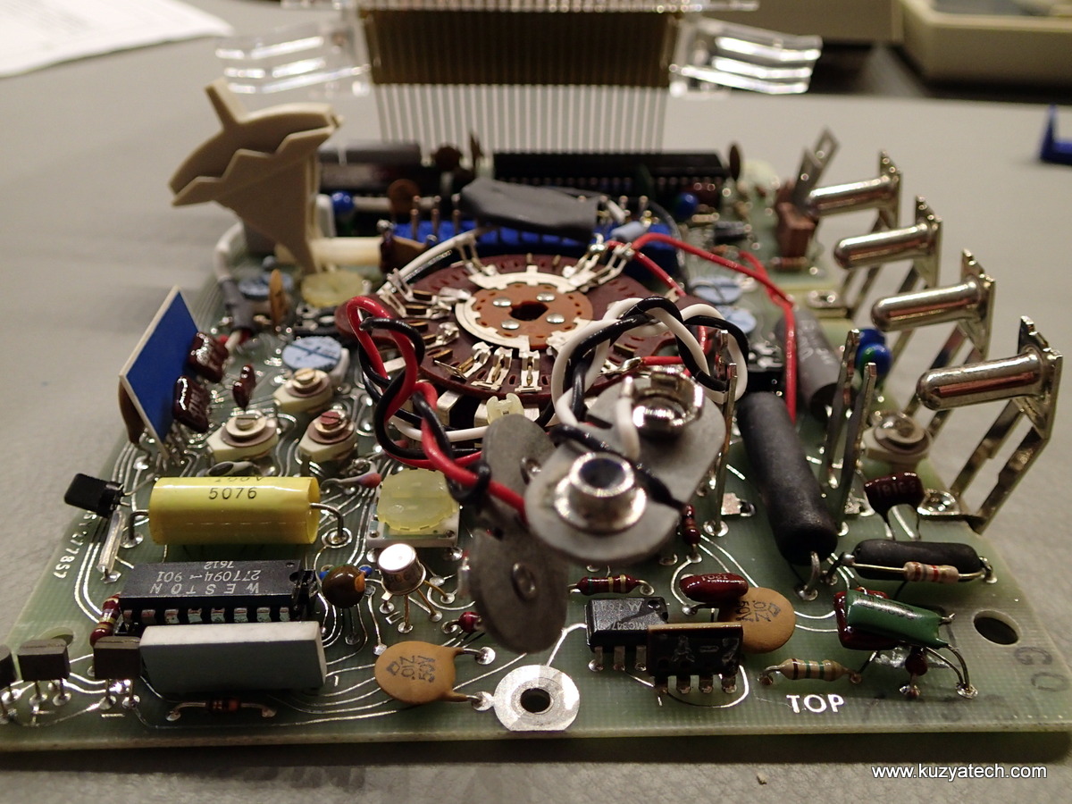
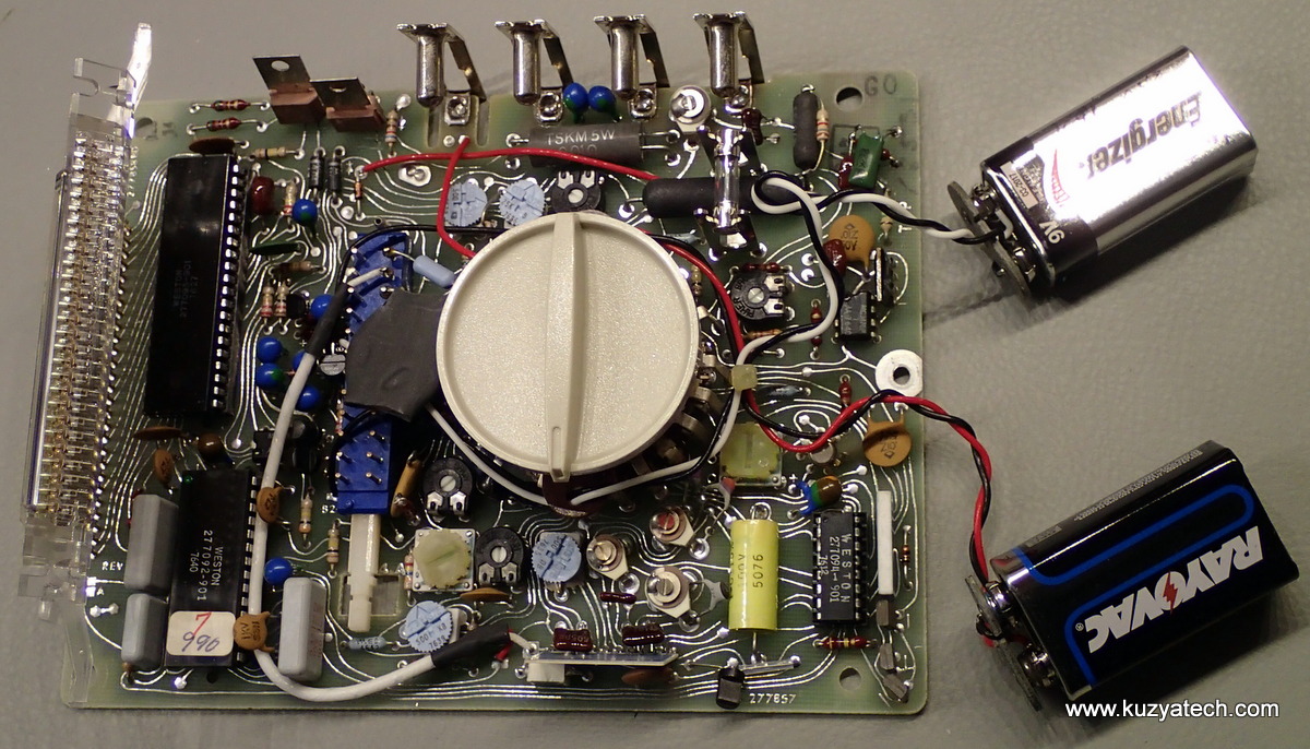
Components
This is mostly an IC based design with Weston branded chips that I am yet to find commercial equivalents of, so if you have any information- feel free to leave it in comments.
The display is driven by a 40 pin DIP 277093-901. It looks similar to ICL710X, but the pinout does not match any existing parts.
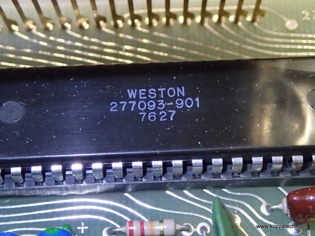
Display driver
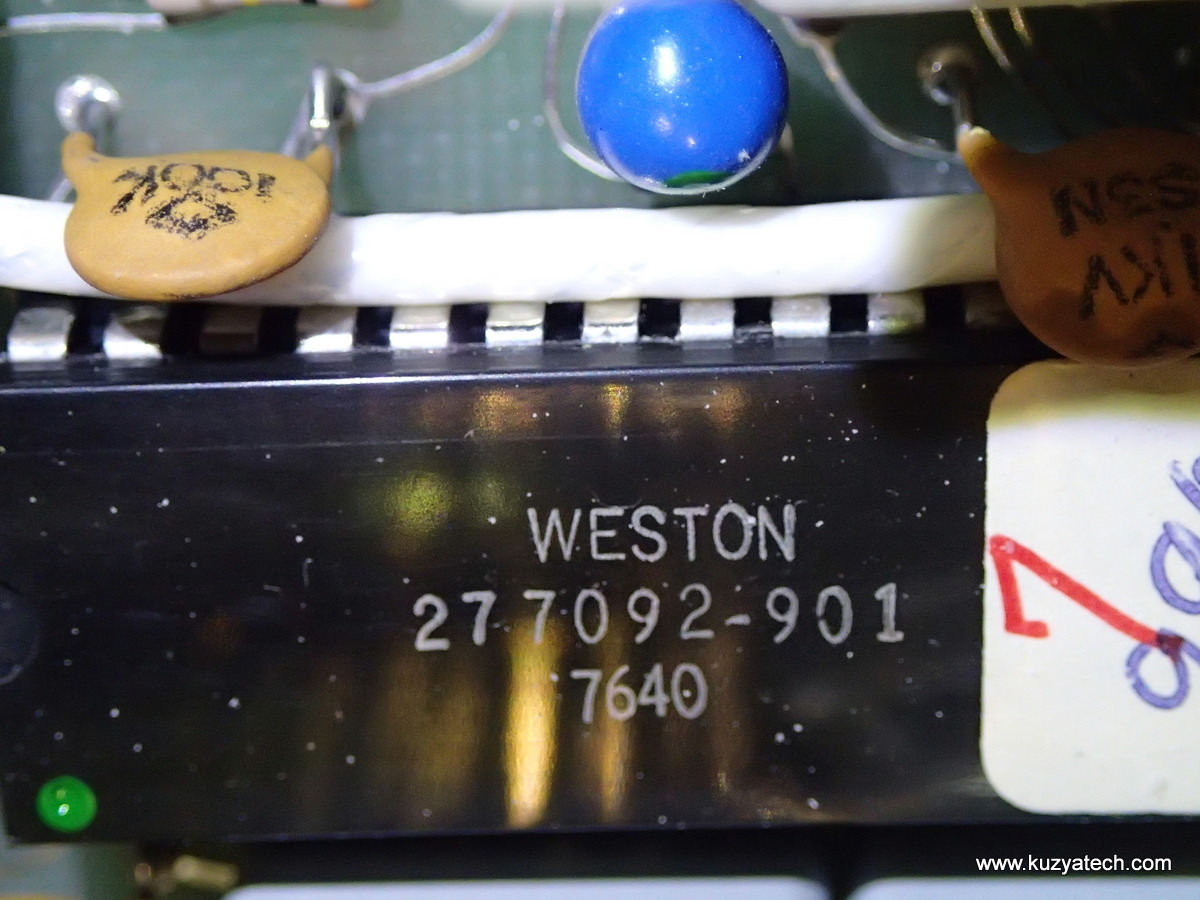
Next to it is a 28 pin DIP 277092-901 with a numbered sticker- I suppose it could be a micro or memory.
At the far end is a 16 pin DIP 277094-901, that seems to be some type of a logic gate .
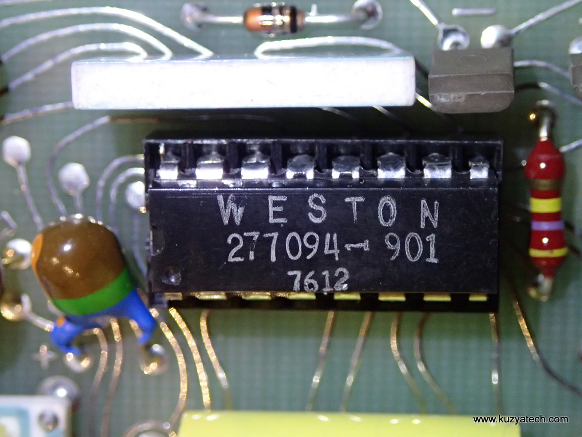
Some type of logic gate, judging by the power/ground pin location and levels on the pins
And finally an 8 pin DIP is a Motorola MC3476 Opamp
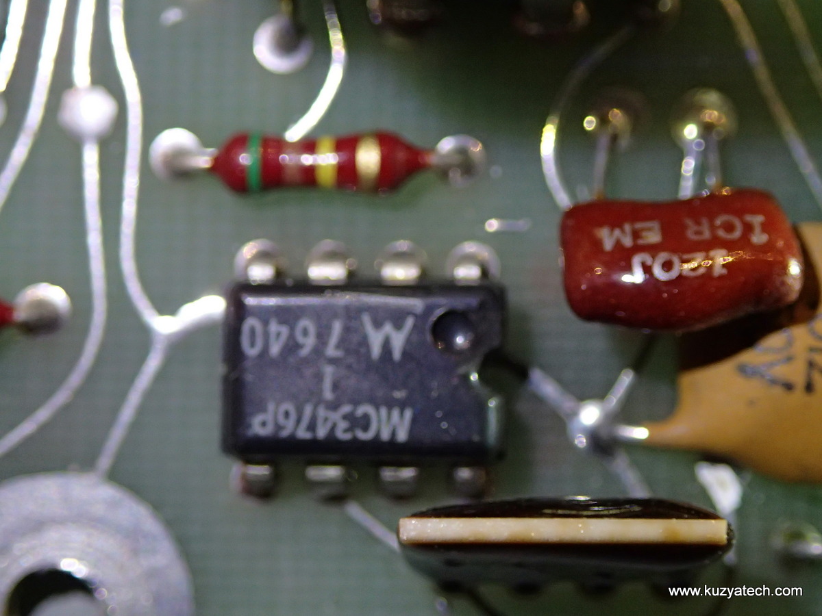
We have an Opamp!
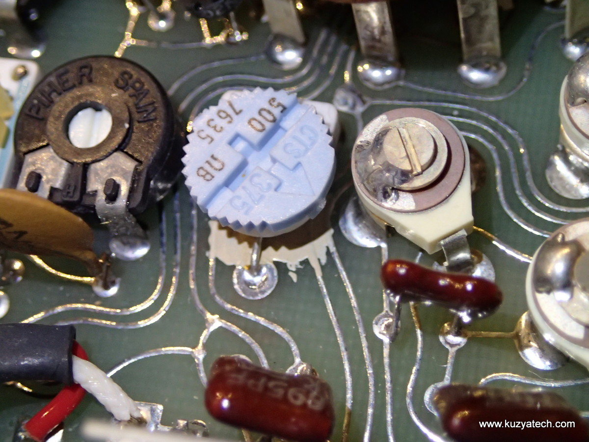
It’s all variable!
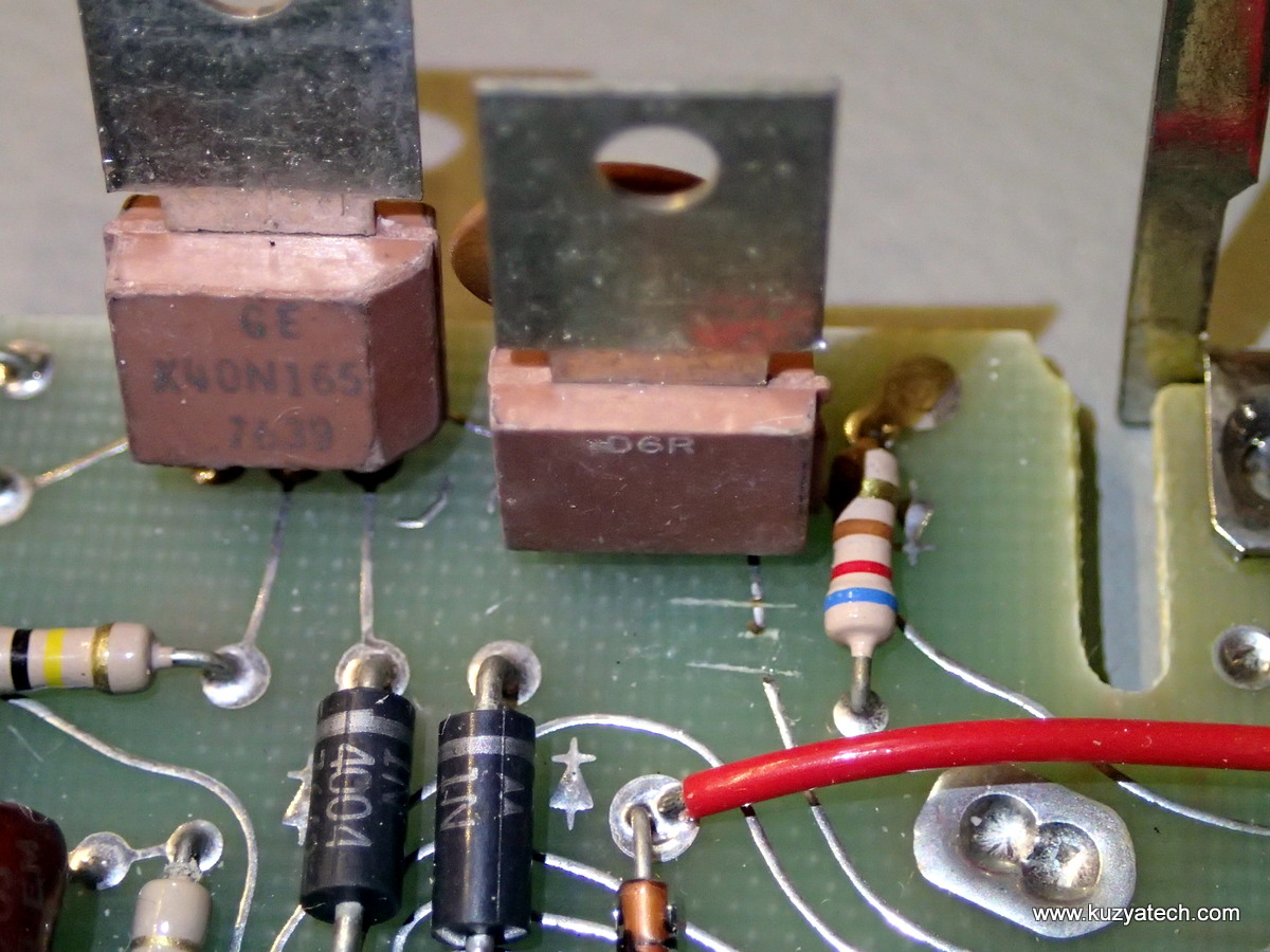
Is that a GE branded transistor?
Seems to be a GE X40N165. Interestingly enough, why is there a trace cut going to the rightmost one? There is also a resistor in a spot marked as a diode. I see no other signs of rework, so will leave it alone for now.
Another canned IC, labeled as a ITS30611. Seeing how it’s got a guard trace around a pin, probably an amplifier of sorts

ITS30611
Troubleshooting.
The meter did come with a user manual, but sadly no schematic, so that will make things a bit more interesting.
On to troubleshooting
User manual cover shows the meter with a positive (ie black numbers on white background) display. The screen here is all black, and does not change with the meter on. Time to break out a scope:
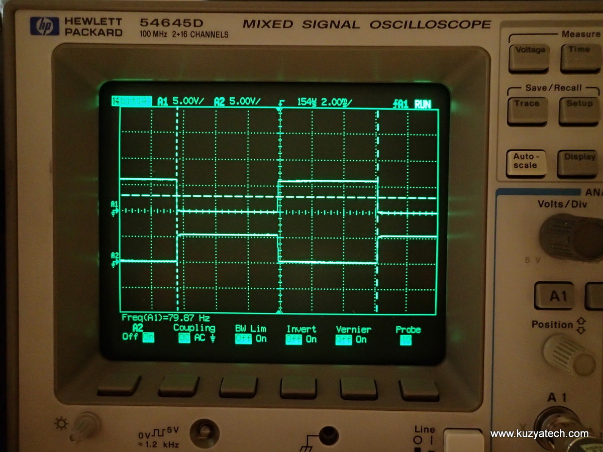
Something is working
Looking at the signals going to the display, I see a normal out of phase 80Hz 5V pattern, so something is trying to drive it. Every few seconds the two signals end up in-phase, indicating possible “blinky indicator” may be going on.
Using an LCD glass from my spare parts bin, I can see the same (Upper right corner of the picture).
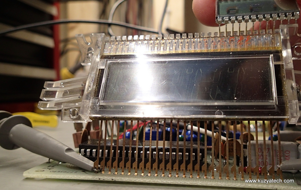
The screen is not looking very healthy. Side-lit with a flashlight to show segments and traces
So it appears the meter is alive and trying to do something but the screen is either not making good contact with the metal strips or is simply not working. I have a few options here:
- Leave it alone as a nice museum piece
- Try cleaning/improving contact under the glass
- Try to find a similarly sized glass with the same pinout (brief scan of Mouser and Digikey did not yield much). The replacement would most likely require desoldering all the metal strips at the board before I can pull the display out of the holder
- Make a replacement display holder board mapping currently manufactured display to the existing pinout.
It would also be nice to know why one of the GE transistors has its Base (or Gate) disconnected, and what their function is in the circuit. There is some digging to be done, so for now enjoy the teardown. To be continued!
Resources:
My age permits me to give you some hints: 1) the 40 pin IC is only a LCD driver. 2) the 28 pin IC is the A/D converter. Look at the 2 quality white rectangular caps near it. 3) the part ITS30611 is a two transistor array for differential amplifier input (two transistors in one case have temp equilibrium, reducing drift). Also one of its pin is surround by guarding ring to preserve high impedance. 4) 16 pin IC might be an analog switch. It is next to the hybrid resistor divider (rectangular white top/green body part).
However all parts except 1 & 2 may not be responsible for the blank display. Look for traces between 40 and 24 pin ICs, might communicate with 8 bit parallel bus. Check for signals with the scope you have.
I love restoring vintage equipment like you. If something else comes in mind I will post to you again. Good luck.
Thanks for the info! I think display problem is the LCD itself, since I see drive signals on its pins and can get blinking segments on a modern LCD if I connect it instead. It also seems the screen is not supposed to be normally dark.
99 percent were bad lcds. I worked for Weston and repaired many of the 6000. I have one like new but a dud lcd and they were gone about 2 years after Weston was bought out but EIL which I worked for as a service manager.
Great teardown. The width of the thing sure doesn’t make it a great “hand held” meter! I love the artistic hand drawn traces.
Pingback: Vintage Multimeter Teardown – Weston 6000 - Hacked Gadgets – DIY Tech Blog
Pingback: Vintage Multimeter Teardown – Weston 6000 | Hi-tech news
I know this is an old post, but I thought you’d appreciate a reply. I worked at Weston, and was a junior engineer doing support work on this model 6000 product about 38 years ago… The two Weston-p/n-marked chips are both custom integrated circuits designed by Weston, and probably can’t be replaced now because they’re just too old. That pair of custom-chips make a two-chip analog.A/D converter and digital logic/LCD driver pair, and predates the single-chip LCD 710x A/D. (They also do more, because they handle autoranging and a variety of other switching.) The transistors that have one lead chopped off are being used as a protective device, utilizing the reverse-base-tunneling voltage of the part as a low-leakage-current overvoltage protection. (The tunneling threshold voltage is poorly controlled, but the reverse leakage current is superb.) And last but not least, the LCD is also a custom designed part because this instrument predates any of the “standard” LCD pinouts that became more common a few years later… So you probably won’t be able to replace the LCD either. As you say, it’s a nice museum-piece, but probably no longer useful as a repairable instrument just because replacement parts no longer exist. Sorry for the bad news. Best regards.
— John Berting 15-Jan-2015
Oh yeah, one more thing… That dark display background is caused when the thermoplastic or frit seal around the perimeter of the LCD degrades and leaks air into the LCD. The liquid crystal inside the display becomes contaminated (or leaks out). With a bad liquid crystal you’re just looking at a pair of crossed polarizers, so everything is dark… Nothing to be done about that kind of failure except to replace the display. (Unless you are really friendly with an LCD manufacturer who would unseal, clean, reload the liquid crystal material, and reseal the display. I’m skeptical…)
— John Berting
Awesome,thank you for your insight, John!
I was given one by my brother in law who was a electrician,
Unfortunately he passed away three years ago with prostate cancer,
I would like to sell it and give the proceeds to one of the charity,
If you can help me to sell it at the best price i will appreciate it.
Kind regards,
Brett. M. ( Retired Engineer.)
As above,
I wish to sell one I have.
I would like to sell it & give the whole amount to the Charity. If interested please Email me.
I have one which I would like to sell 7 & give the money to the charity,
I’ve got one that’s “trying” to work – sometimes a full display, then fading to zero.
My grandfather and father were employed at the Weston Electrical plant in Newark, NJ all of their lives. Adam Ohl and “Jack” Ohl. I have a Weston Model 6000 “AutoRanging” digital multimeter, slightly used, with leads wrapped in the original plastic bags, with leather case, in the box, in the original box.
I have a weston model 660 in great condition w/ leather case and handbook. It works good I just used it today and thought I would do a bit of research on it and saw your posts . If you are interested in it contact me and i will send pictures and what ever info you might need as i really don’t need this meter anymore.