Another Hamfest find is the Sinclair Radionics PDM 35 digital multimeter. Having grown up with ZX Sinclair Spectrum clone, and reading a lot about Sir Clive Sinclair and his creation I wasn’t about to walk by this. If the look of it is a bit calculator-like, that’s because they actually reused a calculator enclosure! This was a cheap model, selling for 33 pounds in the 70-s and 80s

It's a calcu-err-meter
My bounty included the meter itself, a user manual (A scan is here), and a set of original probes

Original probes and a user manual with a schematic
All ranges are selected by a slider switch

One slider to rule them all
After shaking out bits of battery compartment foam, and cleaning the stickers off the case. it looks pretty good. A fresh 9V battery and the thing is running.
Top right segment is missing on all digits, but otherwise it seems alive. I fed it a few voltage levels and compared the results to my Fluke 8842A. Both read pretty close. Good enough at this stage! Time to take it apart

Not the cleanest assembly job
A bit messy here- lots of flux, questionable sodler joint. No comparison to the Fluke 8000A I just wrote about in another post. I imagine they served rather different price target markets. Desoldering the four tabs we can now take the board out. The front panel confirms the calculator ancestry of the case:

It was indeed a calculator case

Did anybody hear of flux removers?
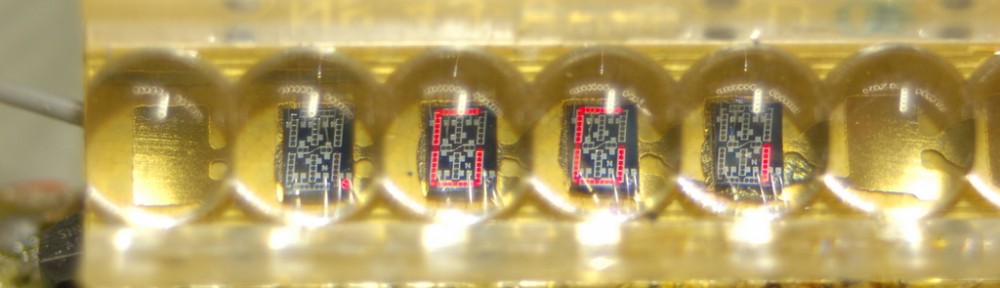
The front of the board is an even bigger mess- I am honestly surprised the thing even powers up! We have AY-5-3507 display driver, LM3900N quad opamp,CD4007AE dual complementary pair with inverter, and an unknown RCA 17898 part. The most interesting part though is the display. It’s an NSA1540A.

It's nice when built-in lenses magnify the die
Looks like the display has lead frame for more digits, but only the four got the actual die. Pins 1 and 2 looks shorted.Pin14 solder joint is suspect. I suppose this is IPC class -1 assembly? And here is a magnified scan of the schematic:

Conclusion:
The meter is quirky enough to keep in my collection, but is not something I’d end up actually using for anything useful.
P.S. There is a discussion of this post over at EEVblog Forum
Hello, so glad I found this site, as it might help me. I have the Minolta version [basically the same device] of this multimeter and it’s in great cosmetic shape. However, since the day it was given to me, I noticed that the display didn’t indicate the polarity [I believe this multimeter doesn’t display a + sign, but it’s supposed to display a – sign, when the polarity is reversed, and a = to indicate: Over Limit… I could be wrong] or the Over Limit. So, I decided to take a peak inside, perhaps it’s something I could fix [I’m just a hobbyist – not an electrician]. It looked pretty clean on the inside, but curiously there appears to be several pins [from different devices like transistors, ICs etc which have been left unsoldered – is that normal practice? Couldn’t that be the issue? I looked up pictures of this multimeter on other sites, and all the points on the circuit boards which require solder, appear to be soldered. I could send you pictures of my multimeter’s PCB, if you think it would help. As I mentioned earlier, I don’t have any professional training, I just try to fix stuff around the house. Please let me know what you think. Any insight would be greatly appreciated. Thank you kindly