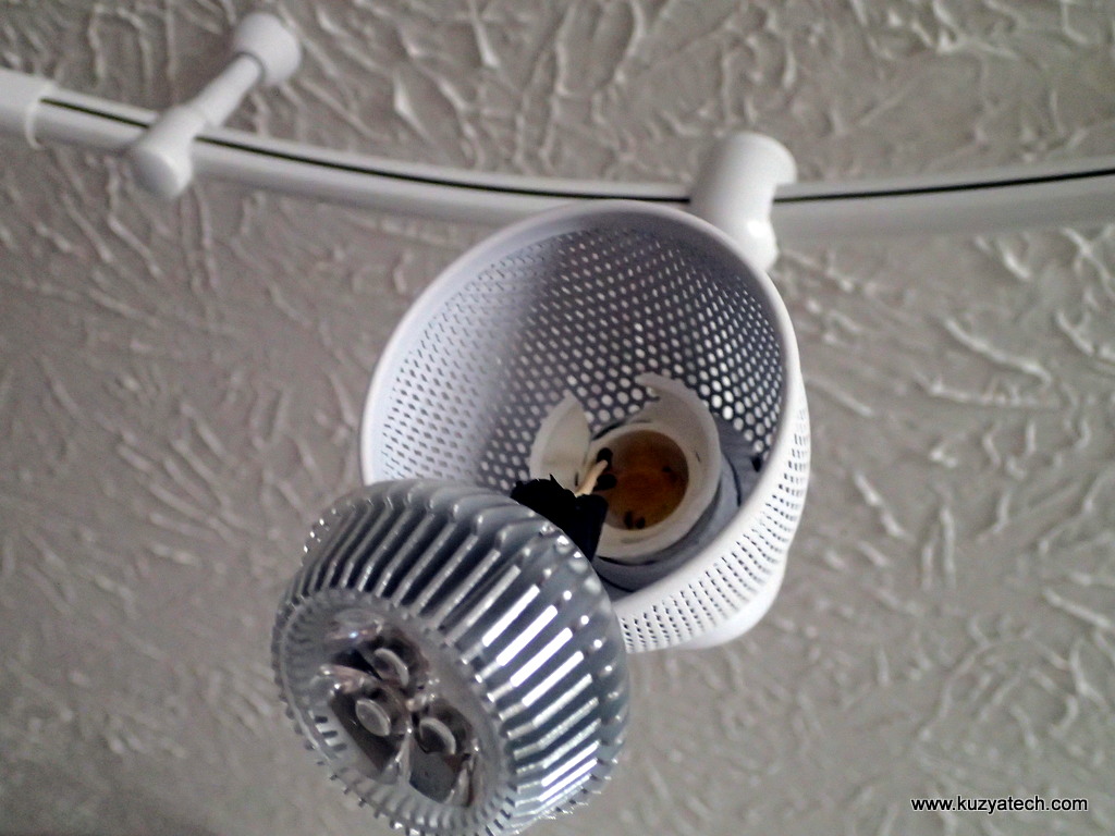
In the usual Kuzyatech fashion, when something breaks, we must take it apart. Today, one of the “early adopter” GU10 style LED lamps decided to fail mechanically:
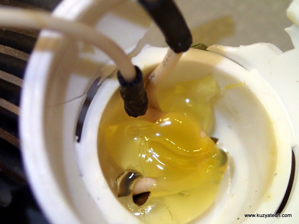
We have a problem
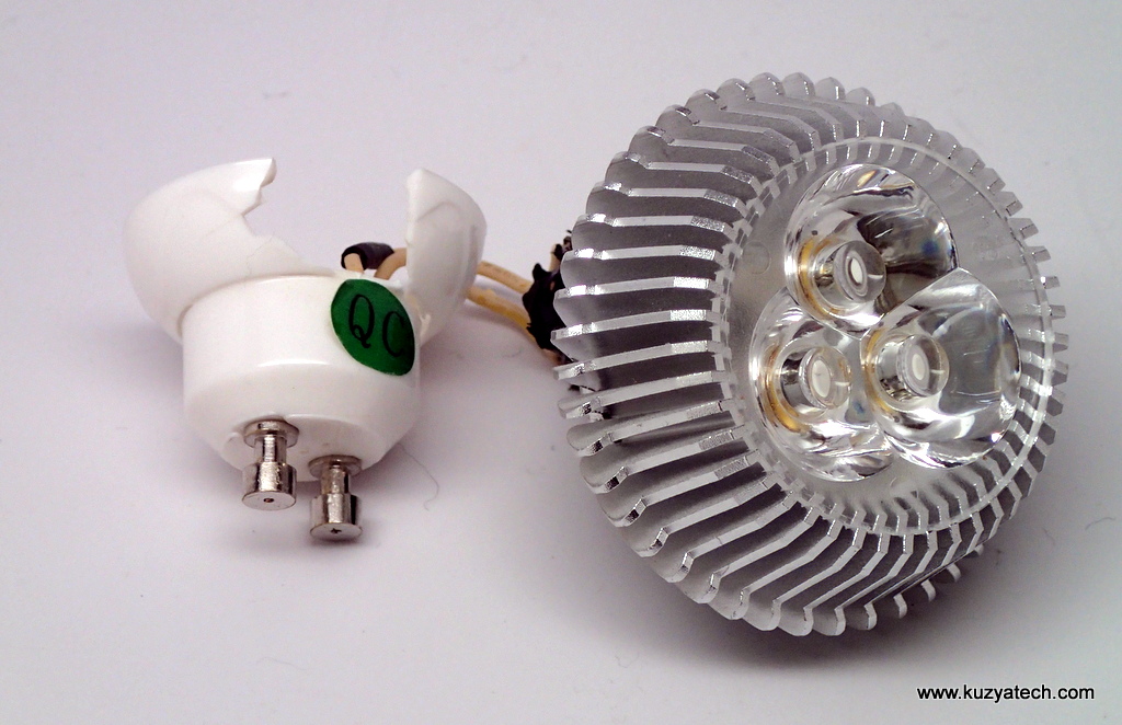
Quality control!
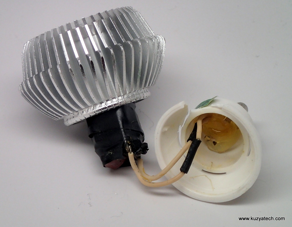
The power supply is wrapped in some tape. But that does not preclude a bunch of exposed mains line points from being visible
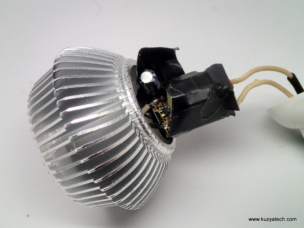
Sure looks like electric tape

Tape removed
“selective” application of the goop
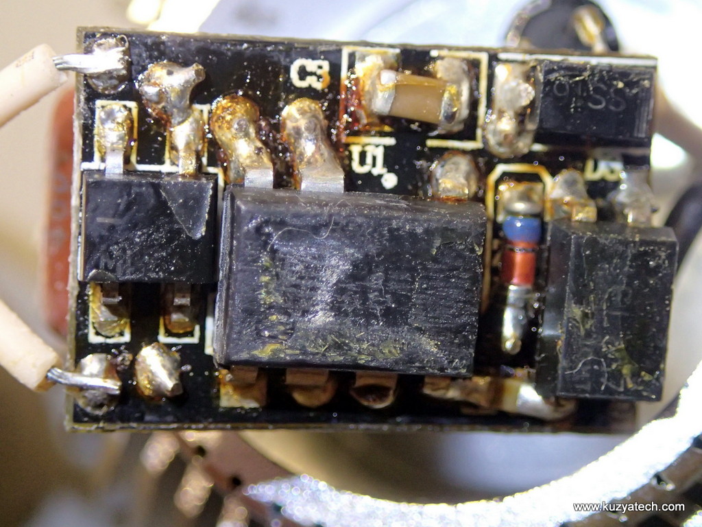
All part numbers sanded off. Diode bridge on the left, controller IC in the middle, optocoupler on the right. Clearance distances- nowhere to be found
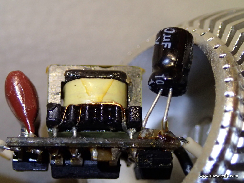
Of course you can solder thruhole Aluminum cap across a ceramic. What’s wrong with that?
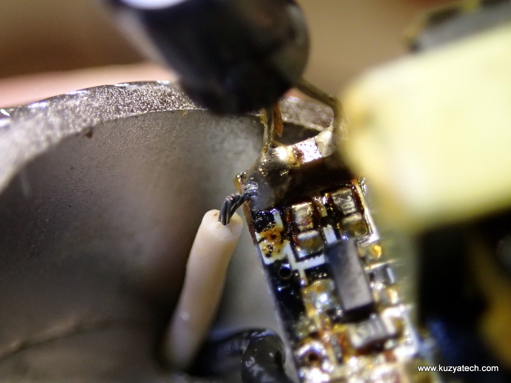
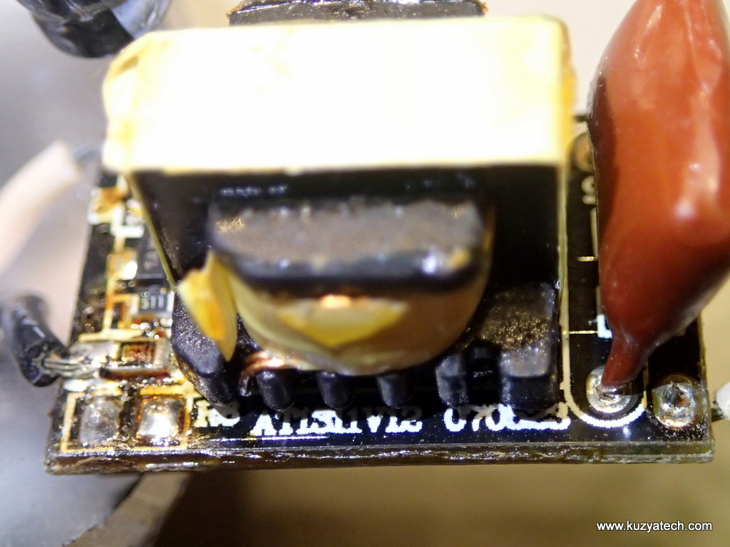
Hey’ it’s still connected!
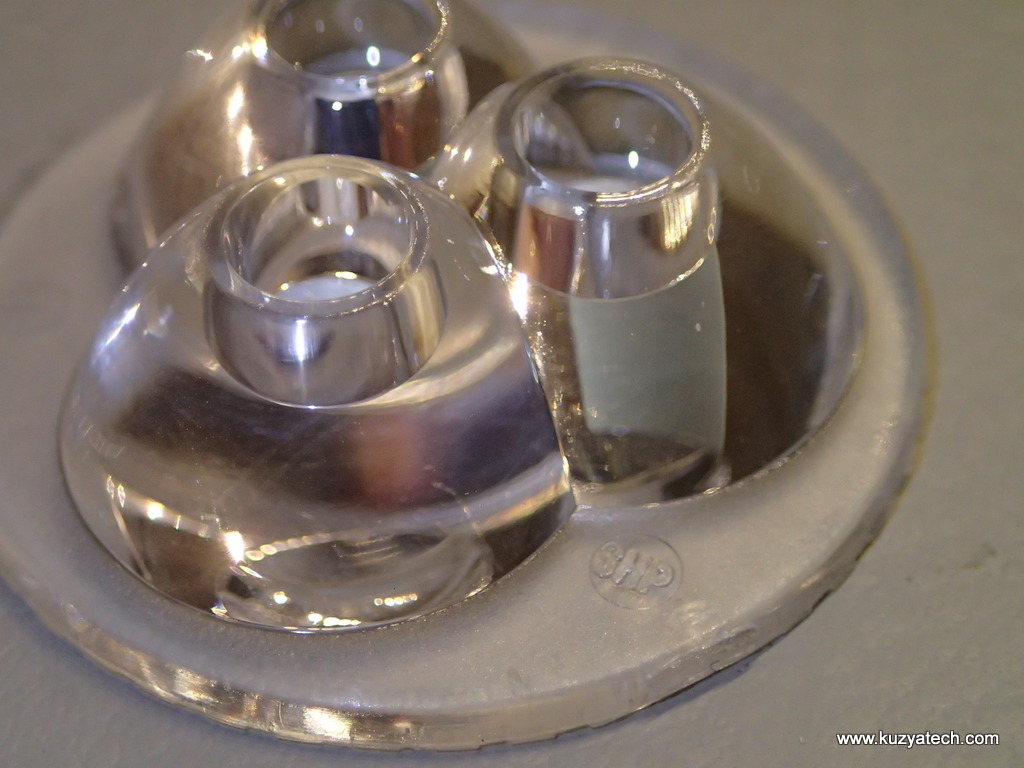
SHP lense
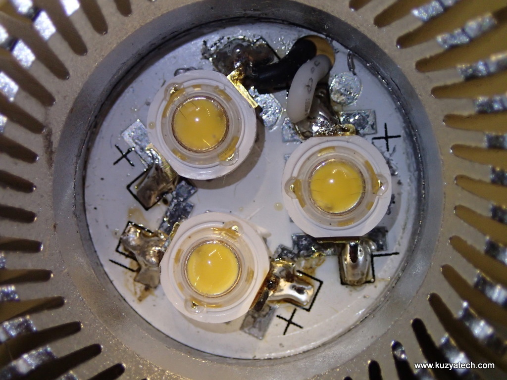
The lamp uses SHP brand Heatsink/lens combination. LEDs appear to be handsoldered to the metal clad board, with very questionable solder joints
And now to the everyone’s favorite part- reversed engineered schematic diagram. What we have here is basically an isolated (if we ignore for a moment the total lack of clearances between various nodes) power supply with voltage and current feedback. The density of parts and their relative location is such that I doubt this will ever pass any safety tests, but it does seem to work. Thinking that this hazard ran for years makes me stop before buying any new no-name lamps!
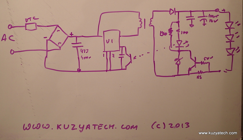
Looks like TinySwitch-II from Power Integrations
http://www.powerint.com
http://www.powerint.com/sites/default/files/product-docs/tny263_268.pdf
I think you have to correct your schematic though 🙂