It’s time to see what the flea market special $5 Fluke 8000A looks like up close

Missing an overlay

For US service phone (206) 774-2206 COLLECT
Step one: clean it up.
After blowing the dust off and cleaning the outside we can now check the basics. Main fuse is intact, current input fuse is blown. That could potentially happen in normal use with a simple overload, so not a sign of troubles just yet.

The fingers on the lower left are a nice diagnostics/test header also used for expansion


The pre-flex era flex. A thin FR4 board bent

there is a certain beauty to this

Current range fuse is on the right, big orange circle- a MOV?

Shield is removed. It was attached to the two spherical posts

That's a nice way to connect. I am being told that's actually an adjustable sense resistor!

Looks to be a mica substrate with a few windings. A precision resistor? Apparently a Kelvin connected Sense resistor

I am assuming these resistors get tweaked at the factory, so they are left socketed

Step two: try powering things up.
Plugged it in, pressed power button- a big nothing in return. No lights or other signs of life. I guess it’s tme to check voltages. Looking at the Service manual courtesy of BAMA (Boat Anchor Manual Archive), there are three main power supplies, +5V, +15V and -15V.

Power supplies section. Notice complete lack of regulation on the +5V line
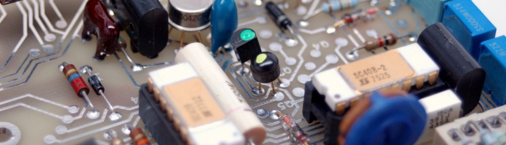
Measuring those I get +5.5V, +15V and -12V. Something also smells hot. That something turns out to be a custom Fluke IC U3 (analog IC as they call it in the manual).

SC408-2 and SC409. Both dated 1975.Unobtainum?
Step three: chasing the troubles.
So we now have a chip that’s running hot. For that it either has to be damaged and drawing more current or be loaded. To test the idea, I remove the IC. Immediately the -15V rail sprang back and became -20V. Ugh, I guess there are other troubles lurking. Now U4 (Digital IC) is getting hot, possibly because of that. Ok, lets remove it as well. Thankfully all DIPs are socketed and are easy to remove. And what do we have now? 15V rail is still +15, -15V is now -23V and what does +5V look like? A nice +6.5V. Not surprisingly U5 SN7447 is now warm and unhappy.

Removing that, we are now left with two analog only ICs that are still cold. In the absence of U5, +5V rises even more. What a nice design! Going back to schematic, it’s easy to see why 5V rail is so load dependent. It’s basically produced the way cheap wall transformers do that- a secondary winding, with a rectifier and a cap. There is simply no regulation! A bit unexpected from Fluke that they’d feed digital logic from such a source. Moving on to -15V, we see Collector of Q19 at -24V, Emitter at -23.5 and a base at -15.5V. The base reference is obviously doing its job, but Q19 is not.

Voltage regulator transistors, Q19 is the dead one, U4 is removed for debug and socket labeled
In a moment of not paying attention I proceeded to desolder a wrong transistor, Q26 instead of Q19. Q26 is a 2N3904, but not your today’s 0.1 cent part:

Gold plated leads and labeled pins. Those were good old days for the lowly 3904!
The original part is 2N4403, a general purpose 600mA PNP transistor.

Nice of them to label pins
Measuring E-C resistance quickly proves that the part is indeed toast:

2N4403 Base to Emitter 5.9 Ohm
The only one I had in my junk bin was 2N3906, rated to 200mA. Figuring I can at least test with it, I swapped it in. Well, now the C B E read as -24.3V -15.5V -14.8V. Much better! At least analog rails are behaving. Placing U3 back in its socket, I have a tiny hope it will stop heating. That of course does not happen. The chip is still uncomfortably hot. We shall consider its magic smoke to have escaped many years ago. Taking U3 out and placing back U4 and U5, I hope to see at least some chips still alive. U4 is cold, but U5 is warm. Which is unsurprising given the 5V rail excursions towards 7-8V. Still no signs of life on the front panel. U4 does not seem to be doing much either- no scanning of the display digits, or segments. Removing U5, and grounding one of the segments while enabling the digit, I can finally light something on the front.

A nice transistor dance. These drive individual digit's common

Custom ICs and segment driver
Another nice surprise was awaiting me when I touched a couple of traces with my finger and got a jolt. Those two traces from the fuse are live and open and are going to the power switch in front.

Nothing like exposed 120VAC fuse and traces
Conclusion: not such a good deal after all.
It seems that there is not much hope for getting this DMM to work again. Individual chips are custom made for Fluke, and being 1974 vintage are a bit expensive to find. U3 sells for at least $20s so does U4. U5 is the only standard part that can be easily replaced. I suppose the other approach would be to recreate the original functionality using a PSOC or a microcontroller, while leaving the rest of the input analog chain intact. That may be a fun project, but will have to wait till another day. While at It, I’d probably throw at least some type of a regulator on the 5V rail!
P.S. There is a discussion of this post over at EEVblog Forum
I have NOS still in original pack Fluke 345496 parts kit which includes U3 for $12 shipped.
I wood like to buy SC S522.
Do you have it ?
I’ll send you a SC408-2 and a SC309, send me your address. there just sitting on my bug board doing nothing
I also have a SC522
Bob Levy
I wood like to buy SC S522.
Do you have it ?
I wood like to buy IC SC522.
Do you have it ?
Hello,
I need a transformer for the Fluke 8000A DMM.
Do you have one?
If yes, then how much will you charge to send it to Cyprus?
Thanks in advance,
Andreas.
if anyone has U3 and U4 they would like to sell….or a couple of above I.C’s….please contact me..
I am investigating the possibility of designing a replacement for U3 and or U4 in this meter. I have designed replacements for custom ICs in the past and this one looks like a fun challange. However, it would be very useful to have a broken IC to decap and examine under the microscope. Do you think you might be willing to donate one or both of your failed ICs to the cause? If so, I am happy to test them both and send you back the good one(s). Contact me if you are interested.
-Matthew
Hello Matthew. Please let me know if you ever got around to designing replacement U3 and U4 chips for the Fluke 8000A series meters. I would be very interested in them if you have. Thanks, James
Dear sir
I receive less than +15 voltage it’s about +10 also the same for -15 and instead of +5 volte I receive +3. the display shows 1999 and It’s not possible to measure anything with it. I really appreciate if you can answer me as soon as possible.
Hallo,
ich suche auch die beiden IC`s für Fluke 8000A.
Die beiden SC 408 und SC 409.
Wenn noch einer die beiden verkaufen möchte ,
bitte mailen.
The prices on these must have gone down. I bought three of these for $5 dollars at a hamfest last year. While all three light up, only one seems to be working. After I get that one aligned, I should have plenty of parts and chips if anyone needs them.
I found one of these a few years ago on a police auction site, got it for 5 bucks plus 13 shipping. When I plugged her in, she came to life and has been serving me well ever since. Talk about longevity! As a matter of a fact, I have been using it this morning to trouble shoot a project I have been building which is not behaving itself. I have been using one of those little yellow 2.99 digital multi-meter from the junk bin at the local hardware shop, but it keeps getting buried in my junk that lays alongside my electric recliner where I spend my days playing with arduinos ESP8266’s and building ghost buster toys for my niece who runs a paranormal investigative service. (OK I don’t buy her beliefs, but it is fun building ghost detectors of different design.)
Just so you know, a working one of these makes amazing music over a nearby AM radio. Like amazing, like, I’ve contemplated using it in a musical production. I can post a recording if anyone is interested.
I would be interested!
I am attempting a restoration of one too. My ic’s are labeled sc322 and 323. Same? Probably. Mine has the rechargeable battery option, which means a Bunch of blue crystally traces and part leads. I notice on your board you have like 3 electrolytic filter caps, mine only has one. This unit is no virgin, someone has soldered a light bulb to the power rail, and there are burnt traces and solder bridges…this is what leads to strokes..
Hello Matthew. I’m trying to repair my Fluke 8000A that had the internal battery option and someone had removed the batteries already before I purchased it. It also has what looks like a light bulb soldered to the power rail as well. I have several of the 8000A meters and this is the first time I’ve see this. I’m curious to know if you were able to get yours working and if you discovered whether or not the light bulb was put in there as some kind of current drain to stabilize that voltage rail?
Pingback: Hamfest acquisition: Fluke 8000A DMM – Imablog