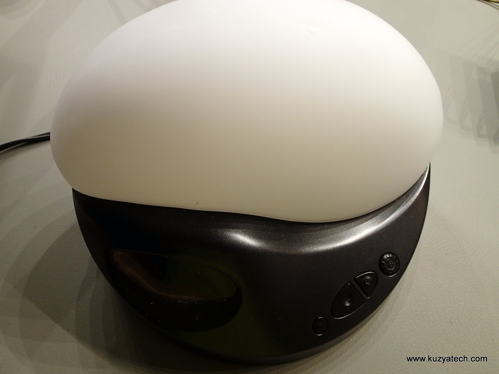
Here is another silly hack I’ve finally got around to do and document. We have a BioBrite SunRise alarm clock at home that nicely simulates sunset and sunrise.The clock is almost perfect with one notable exception- backlight is exceptionally bright even when it dims it for the night mode. This post describes how I fixed that.
Disclaimer- if you attempt to do this, you are doing it at your own risk. There is an AC power supply inside, so make absolutely sure the unit is unplugged and caps had time to discharge before you touch anything.
First, a bit of a teardown:
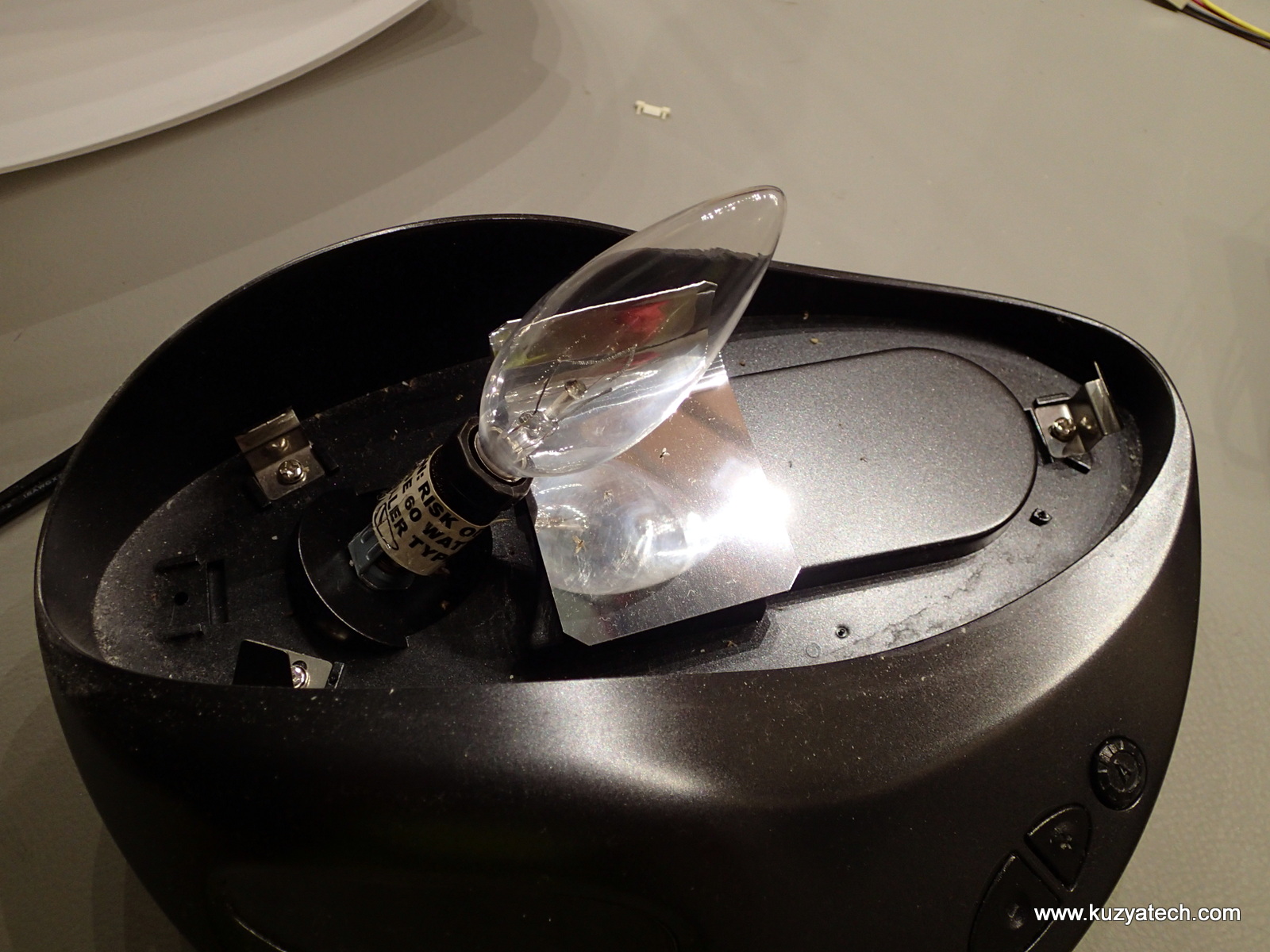
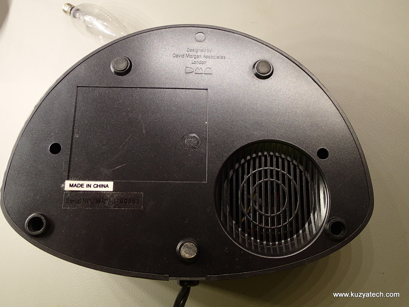
Two screws are hidden under rubber feet, the other two are exposed
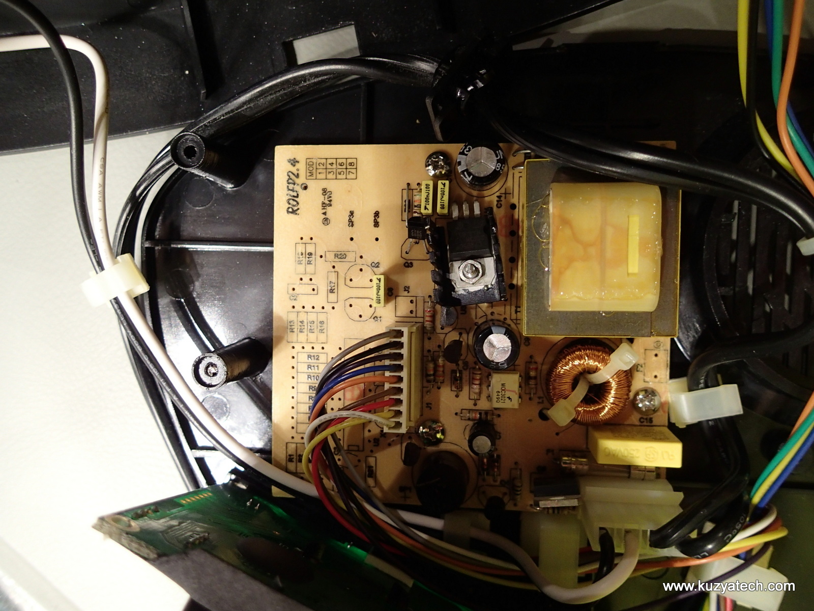
Inside looks reasonably well-made with the design separated into three boards- power supply/AC switch, Display/clock and keypad.
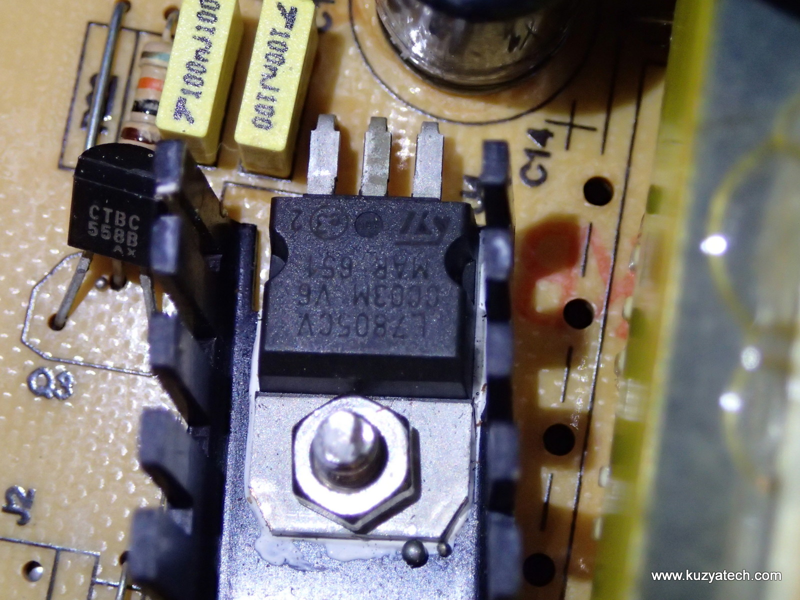
7805 voltage regulator on a heatsink, but where did these solder balls come from?
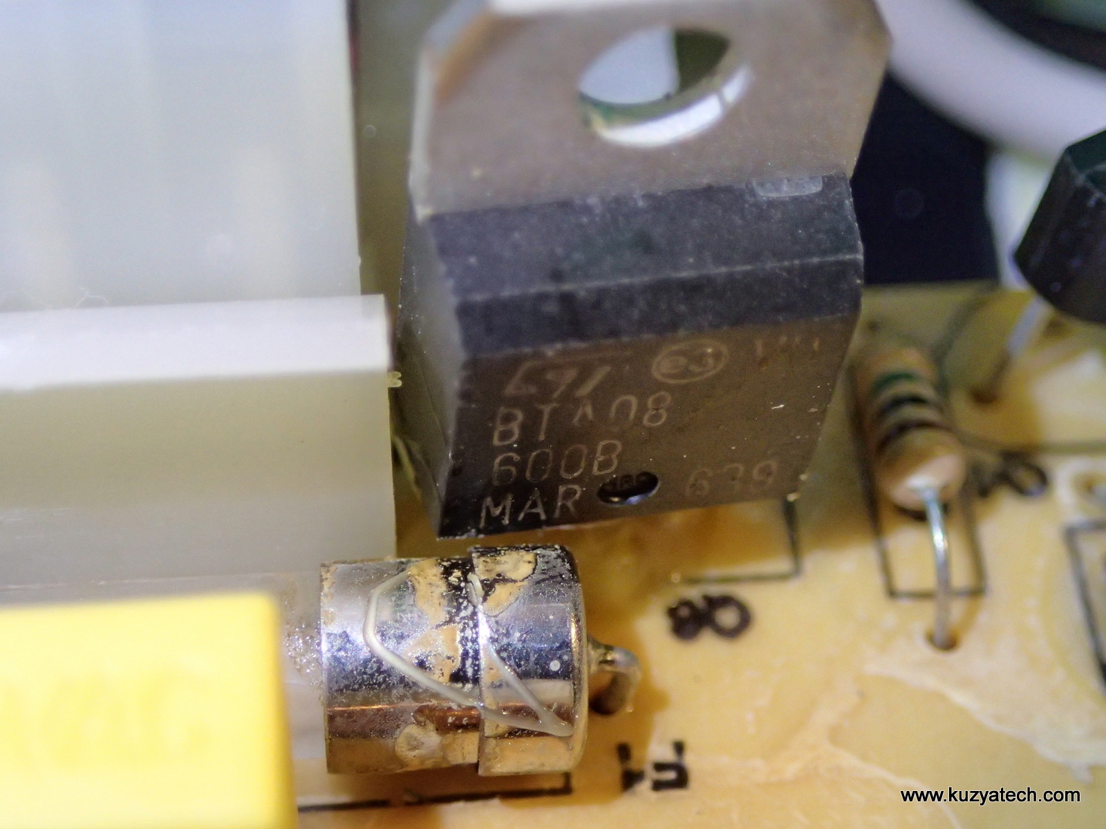
That fuse seems awfully close to the ST Triac
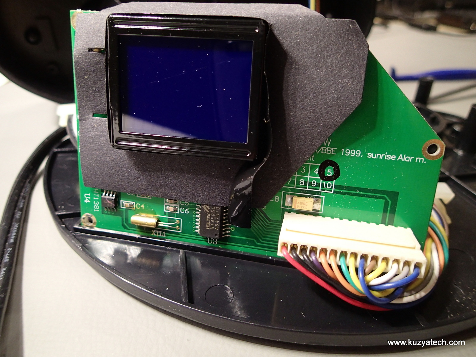
Digital board- yes that actually is the electrical tape wrapped around the screen!
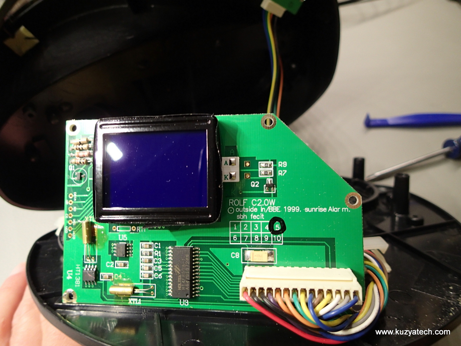 The board is actually an LCD display, extended to add other necessary components. The segment driver is on the back under potting blob. All silicon seems to be from Holtek:
- U3 HT48R50A-1 an OTP 8bit RISC microcontroller driving the show
- U4 HT1381 -serial RTC chip
- U5 HT24LC02 – – small eeprom for storing settings
No major surprises here otherwise
Backlight control
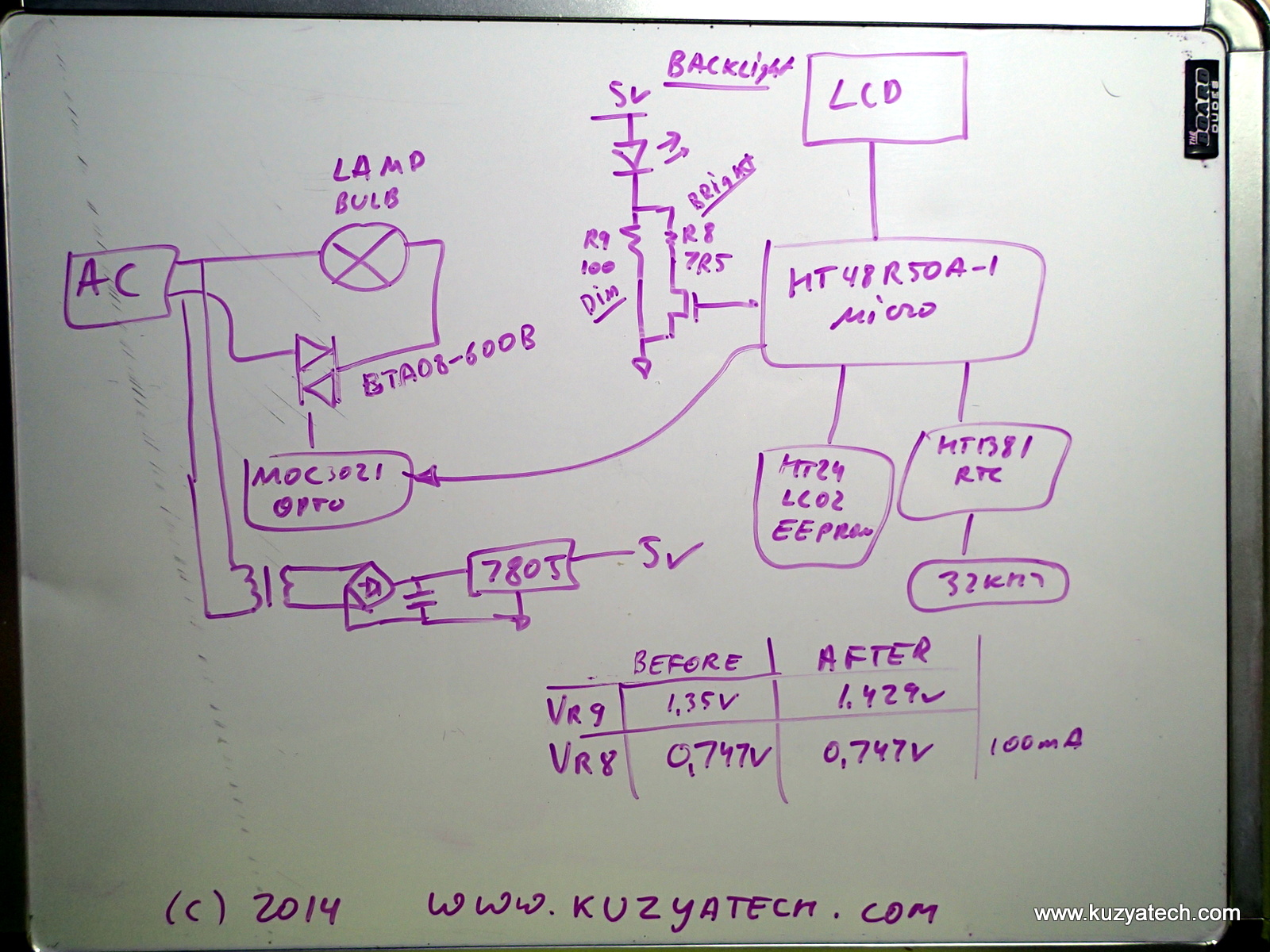
And now we can see what we came for- the LED backlight pins on the board. It appears that Anode is getting 5V directly, and the Cathode is grounded either through a 100 Ohm resistor R9 , or through R9 in parallel with R8 (7.5 Ohm that’s switched by a FET Q2. Measuring voltages, we get 0.75V on Cathode when in normal (Daylight) mode, or about 100mA LED current. When in night mode, we get 1.35V or about 13.5mA. Seems simple enough- R9 sets night mode current so we just adjust it up until the brightness is low enough for a dark room. Original parts were 0805 sized resistors, so after digging around in my junk pile, I’ve noticed something suitable on the old HP board:
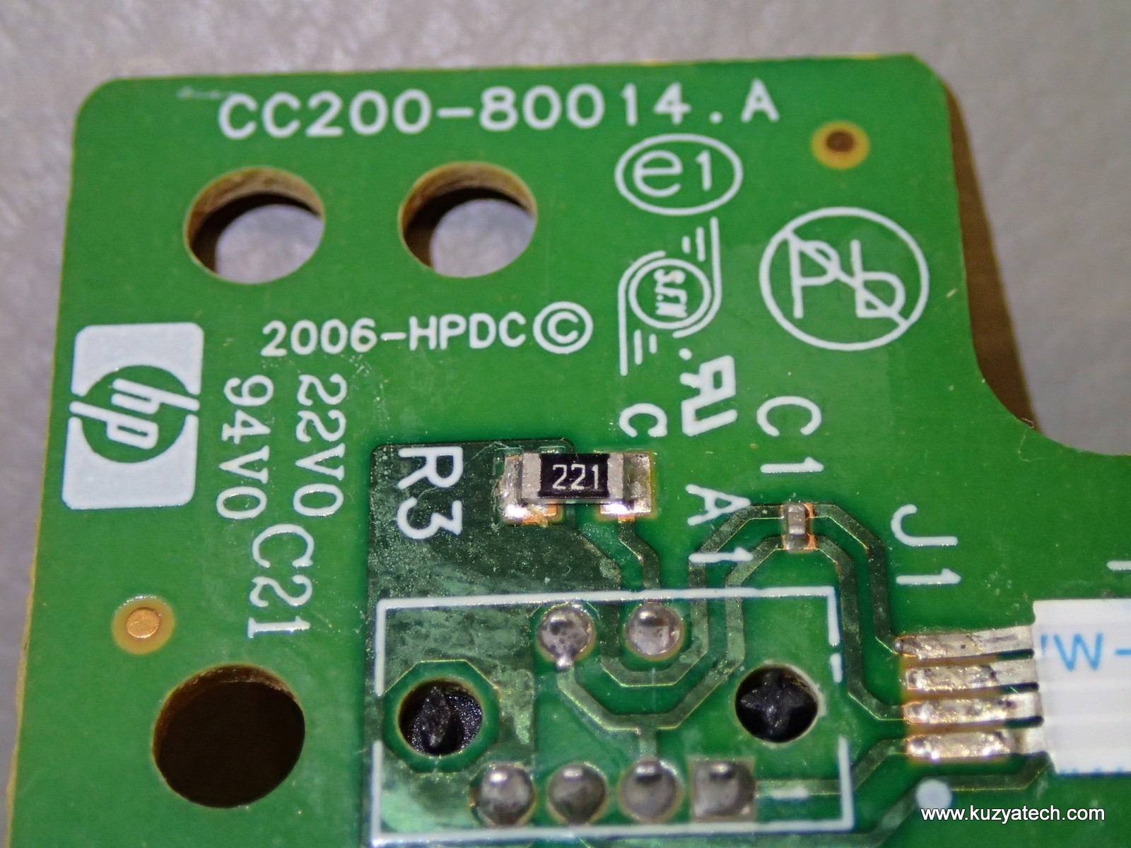
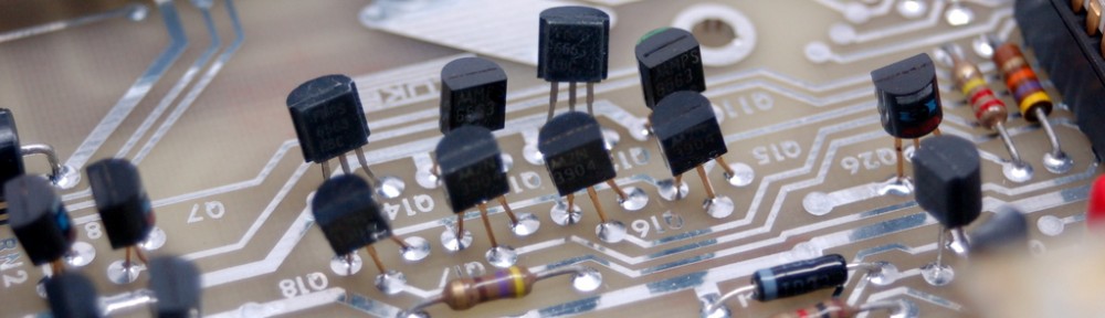
Handy source for 220 Ohm 0805 resistor
Transplanting the resistor in place of R9 we now get about 1.43V across 220 ohms or 6.5mA. At 1/2 the current we’ll usually get 1/2 the brightness from the LED and it sure looks much dimmer. Turning the night mode off we still get reasonably high backlight current, though the effective resistance is now a tiny bit higher (7.25 vs 6.9 when counting the two resistors in parallel). One may suggest adding a potentiometer in place of R9 to make brightness adjustable, but realistically I just need it low enough not to wake me up. And once set, I don’t plan on touching it again:
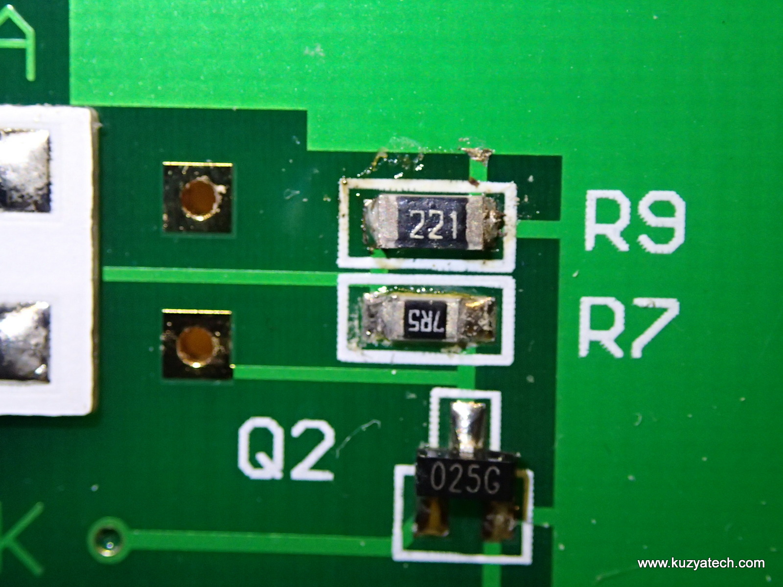
New R9 value installed.
Block diagram
And now on to the everyone’s favorite section- a hand-drawn block diagram of the clock: