
I’ve been working recently on a new top secret project that used multiple slots in the board. Normally I just define them as slotted pads in Altium and the board house deals with it.
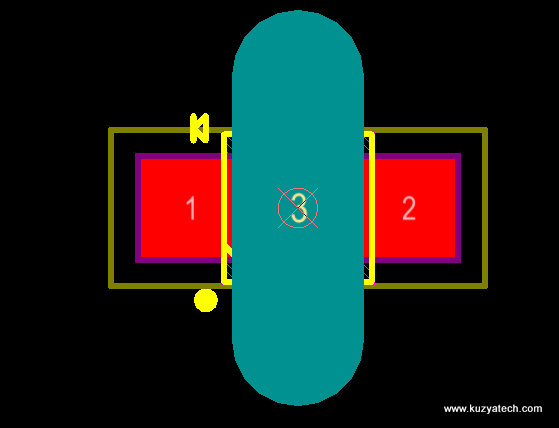
Standard slot as a pad
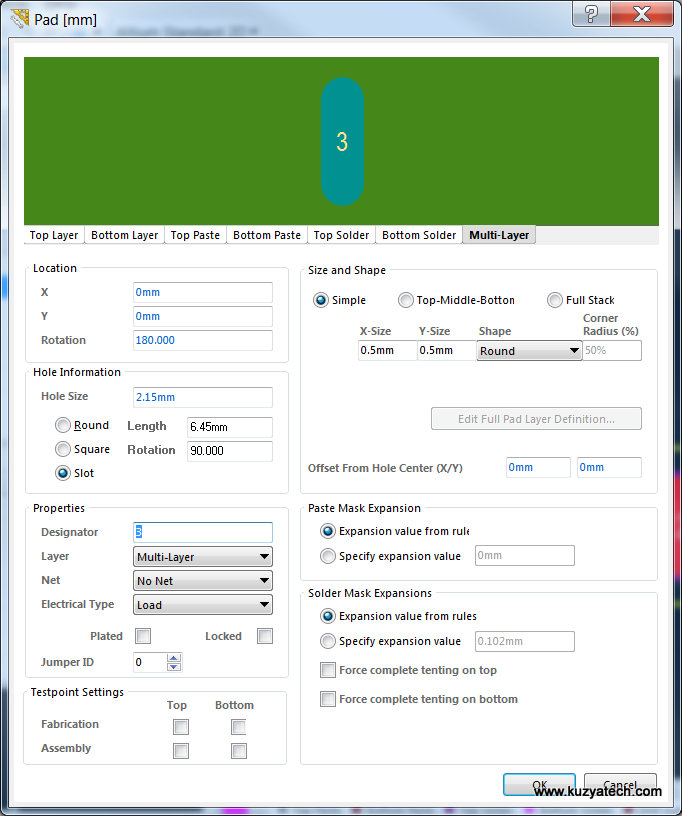
Usually I just add a pad that’s defined as a slot with a very small pad in the middle
This time I was using OSH Park, and as it turned out things were not that easy. Their process does not support milled slots in the drill file. Instead slot outlines need to be on the board outline layer, and at least 100 mills wide. After a bit of fiddling, here is how I got there (This assumes you have the part footprint open for editing in PCB Library editor) :
- Draw a closed outline of the slot on the keepout layer, making sure it’s 100mil or wider. This also helps making sure polygon pours stay away.
Draw slot outline on keepout layer
- Go to Tools> Convert>Create Region from Selected Primitives
- Click on the newly created region and check “Board Cutout” box
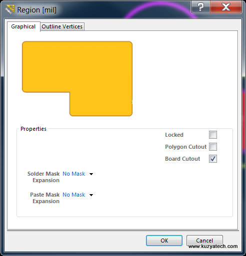
Making region a board cutout
- Add “CUTOUT” text inside the cutout on the keepout layer
- Update your parts from the library or place your new parts
- Do placement/routing/design rule checks
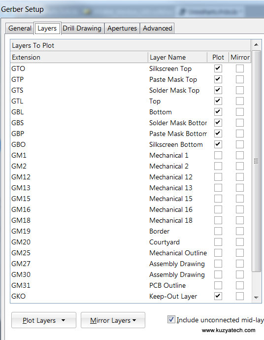
- When generating Gerbers, go under Gerber Setup>Layers and make sure to check Plot box near Keep-Out-Layer GKO. This will be your board outline/slots drawing for Oshpark
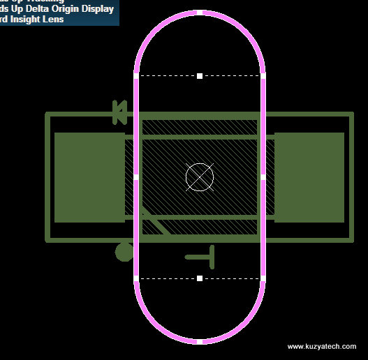
- Check Gerbers and confirm that GKO layer now contains outlines for the slots:
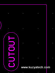
Section of Keepout layer showing board outline, slots and the text for the fab
- Submit files as usually
Big Disclaimer(s)- I am yet to receive my boards back, so while it appears everything satisfies the specs, I may be completely wrong and the boards will be ruined. I’ll post an update once they come in. The directions are for Altium 13, so if you use 14, some menus may look different. My keepout layer contains board outline as I generate that from board shape by default.
Did you get the boards back? I have had to do some ‘post process dremelling’ work on a few boards because of this issue.
Yes, and they looked reasonably good!