The new version of LM317 voltage regulator kit (Rev B1) is finally here. This version implements a few useful enhancement over the A1 release making it a much more versatile board. The kit is available on Tindie– the marketplace for makers.
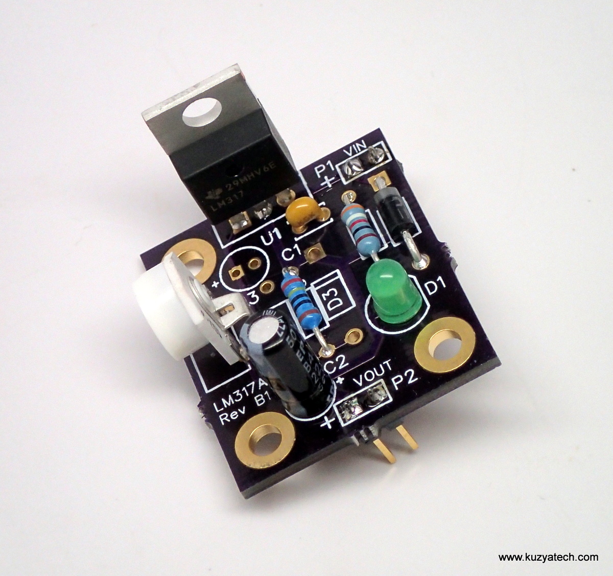
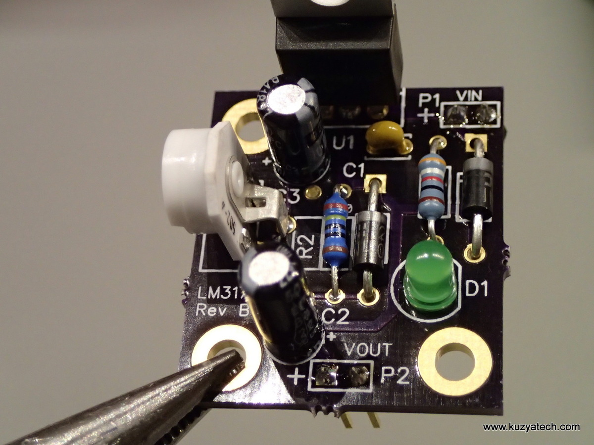
Assembled kit
Changes:
- Add mounting holes- a biggie! There are now three mounting holes sized for 4-40 screws (3.2mm diameter hole)
- Move LM317 regulator to board edge, so it can be mounted on a heatsink
- Add ability to adjust voltage: you now get a choice to either use an included 5K potentiometer for adjustable voltage or install a resistor instead to get fixed output. The values for 3.3V, 5V and 8V are still included
- Add protection diode to handle shorts on the input.
- Add cap to the feedback pin (together with a protection diode) to lower output ripple if desired as per appnotes.
Kit contents:
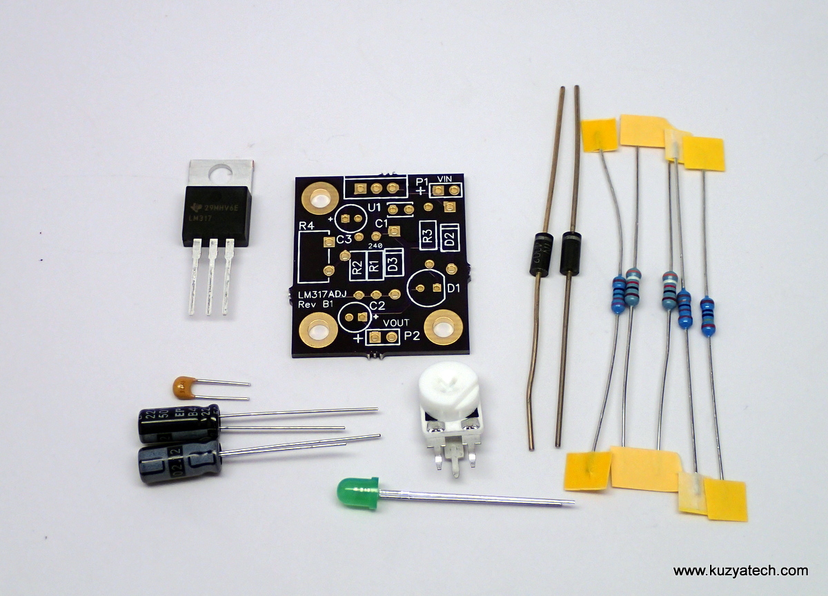
Kit contents:
Each kit contains the following components:
| Reference | Value | Qty |
| PCB | LM317ADJ Rev B1 | 1 |
| C1 | CAP 0.1uF 50V X7R 2.5mm | 1 |
| C2,C3 | CAP 22uF 50V 5x11mm | 2 |
| R1 | RES 240 Ohm 1% 0.25W | 1 |
| R2,R3 | RES 392 Ohm 1% 0.25W | 2 |
| R2a | RES 715 Ohm 1% 0.25W | 1 |
| R2b | RES 1.3k Ohm 1% 0.25W | 1 |
| R4 | POTENTIOMETER 5K | 1 |
| D2,D3 | 1N4002 | 2 |
| U1 | LM317 | 1 |
| Pin headers | 0.1″ pins | 4 |
Documentation:
Assembly instructions in pictures:
Basic configuration
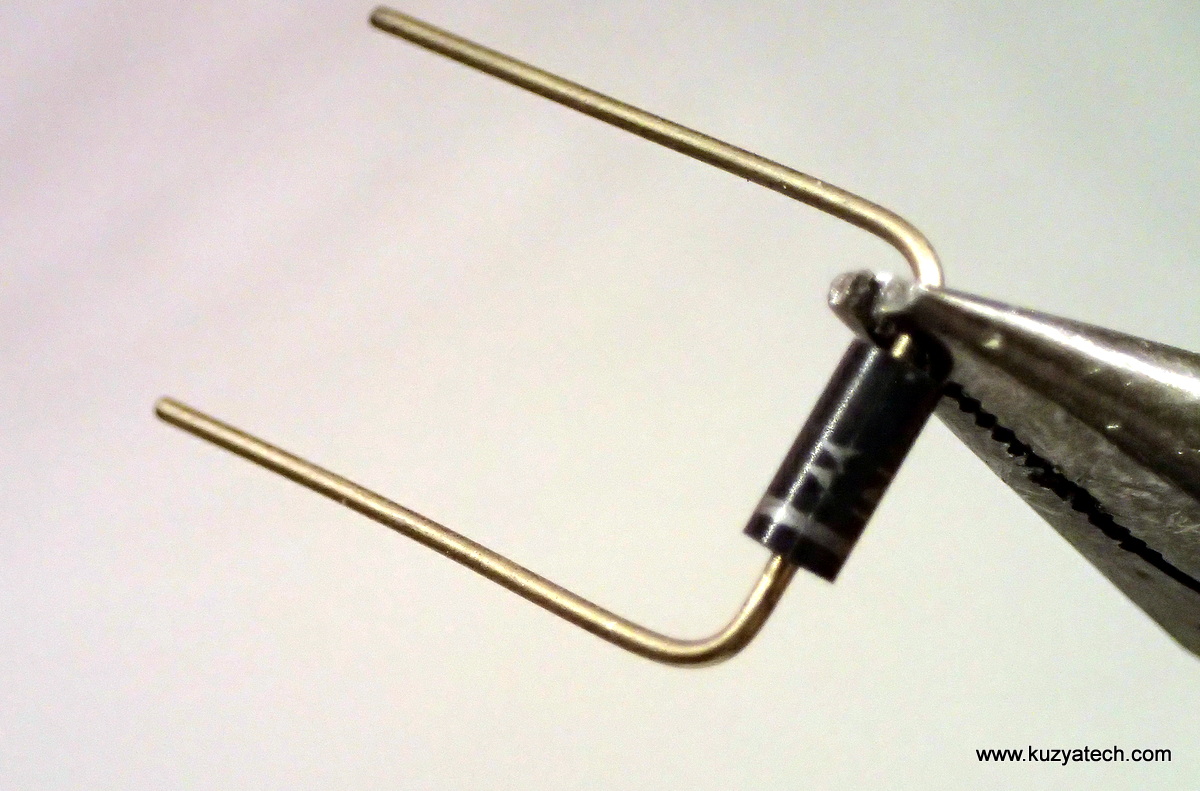
First, prepare leaded parts by bending their leads
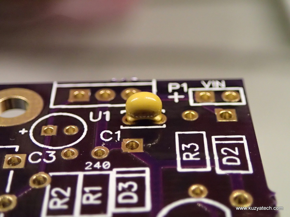
Install cap C1

Install R1
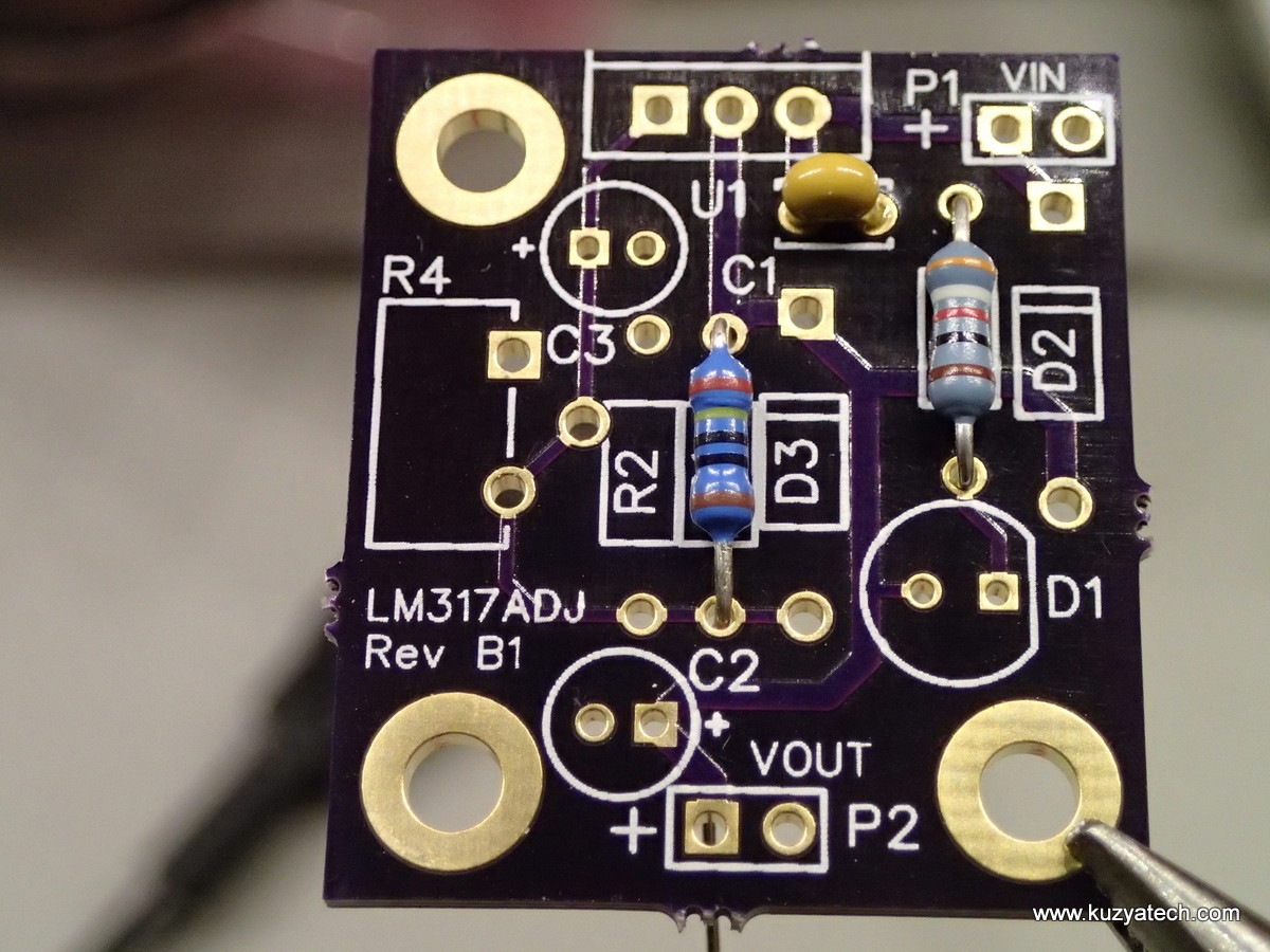
Install R3
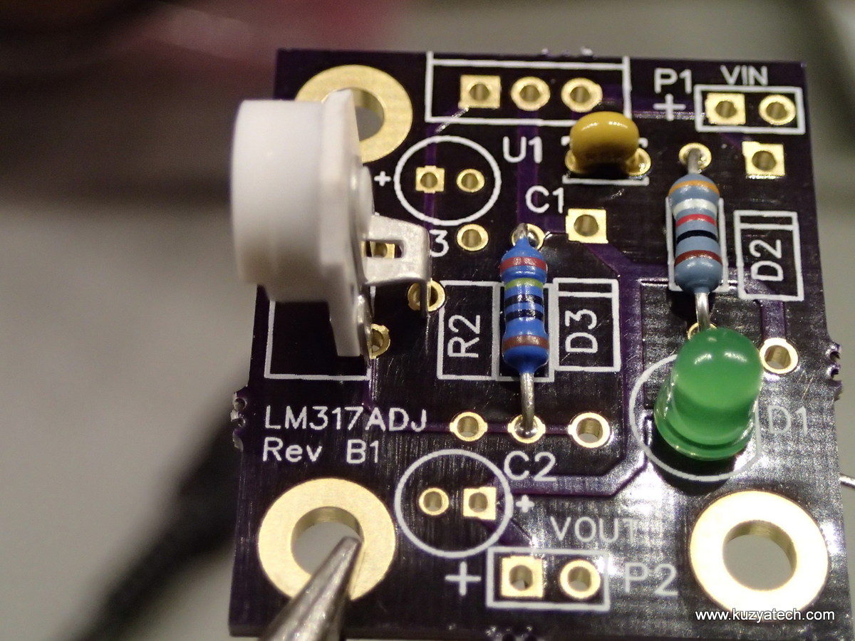
Install LED D1, making sure to orient the flat side to match silkscreen. Install potentiometer R4 OR resistor R2, but not both
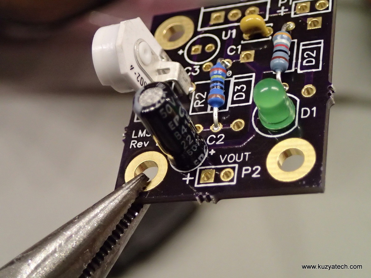
Install output cap C2. Note the polarity!

Install diode D2. Note polarity!
This concludes the basic configuration of the board. The board is now useable.
Complete configuration:
Complete population: add diode D3 and cap C3. This is normally not required and is provided as an option