Today’s post is a bit of a challenge to myself- what (if anything ) can be learned from analyzing a simple thing like a garage opener button wall button?
Well, we know for starters it has an LED inside and is also able to control a garage opener.
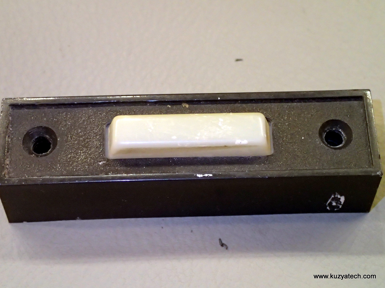
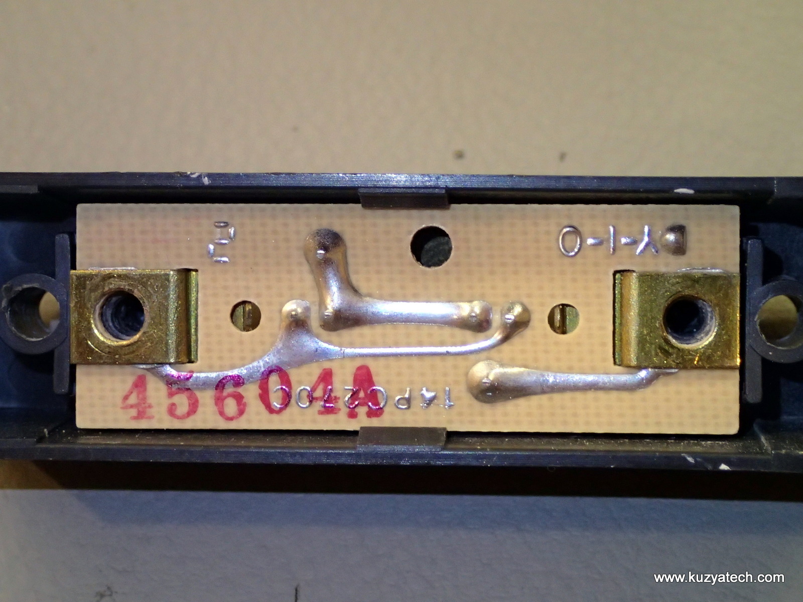
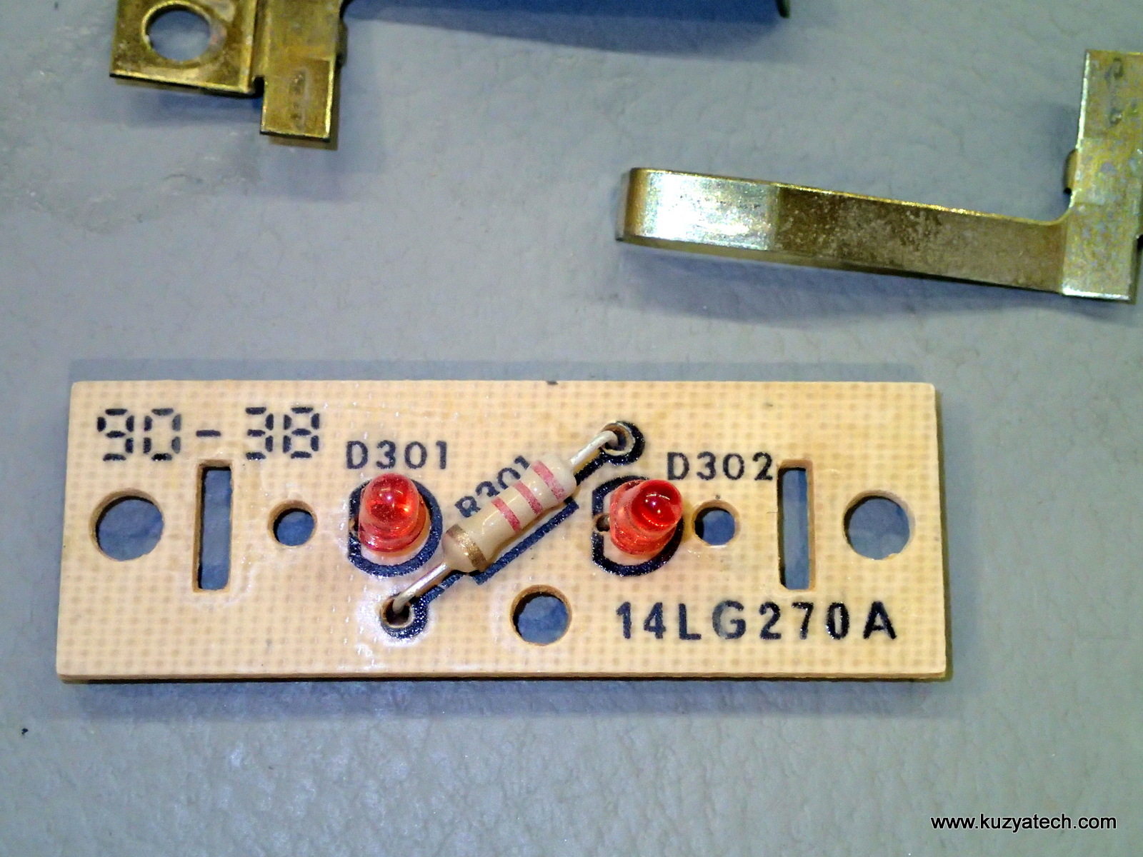
Week 38 of 1990 construction, one resistor and two LEDs back to back- probably to handle reverse wiring polarity or AC signal. Everything is in parallel, so whatever signal is coming from the opener to sense button press is also used to feed the LEDs. Single sided board, switch is made from two stamped contacts that also serve as wire lugs. Notice how all the parts server multiple functions: the same screws that hold the wires also press the contacts into the board and hold the whole thing together. Oddly enough, the designers felt it was necessary to have two sets of contacts handling the button press. It may be to allow for center LED location, or to keep the button feel symmetric.
Now, let us take a look at bit more modern version.
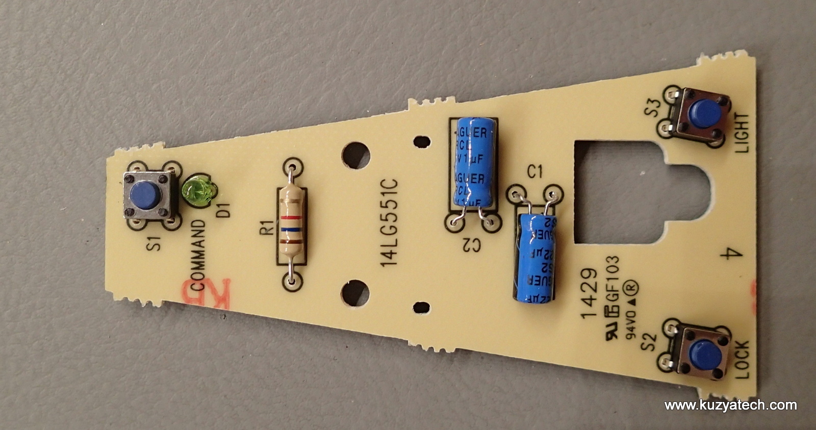
This one adds a much larger backlit button and two separate ones to control lights and also disable opener’s RF receiver when the owner is away. All done over the same two wires.
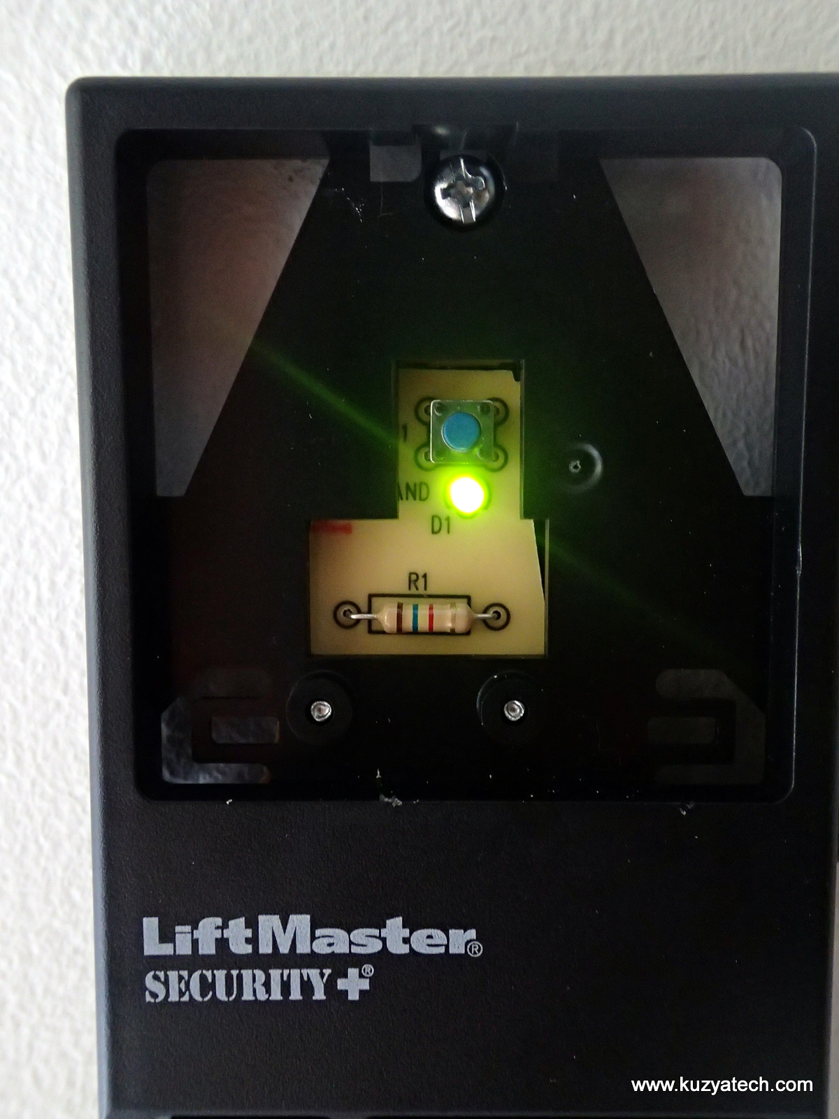
Same LED/resistor across the contacts as before. Each of the two additional buttons connects a cap of different value across the wires: C1 is 1uF, C2 is 22uF. From there it’s an opener’s job to figure out which button is pressed. All presses will look the same to it. as a line going down, the releases will not. And depending on the time constant of the cap and rest of the circuit it’s connected too, each of the three buttons will take a different amount of time to reach the initial level on the input. All one has to do is measure that time (or slope) and two wires now magically handle three buttons. Among other improvements, the new version now uses tactile switches instead of the contacts
The design is still very much done to price: the two smaller buttons are actually parts of the case frame, flexing plastic when activated. It costs nothing on the BOM but does result in somewhat ugly gaps between them and the main case body:
The main button cover is removable by necessity- to allow for a different color and also to expose mounting screws. Bending case tabs are still used to allow it to move:
Summary
So what have we learned:
- You can keep making essentially the same thing for 25 years as long as you update its look once in a while
- To design for cheap/mass produced market, combine functions of components
- GPIO is very future proof- you can always signal more things over the same two wire
- Yes, you can still use a single sided through-hole board in 21-st century







Pingback: Some Simple Button Switches, Torn Down and Deconstructed « Adafruit Industries – Makers, hackers, artists, designers and engineers!