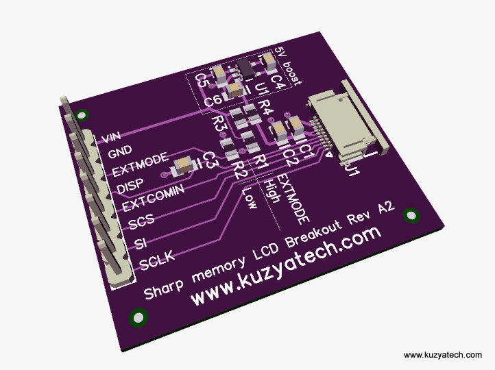
I’ve been tweaking my Sharp LCD breakout board to make it suitable to more users. The latest iteration is off to the board house, but here is a quick preview:
Changes include some manufacturability improvements as well as addition of the optional micropower boost converter. With that, the board can use a 5V LCD and run off 3.3 or 5V, depending on the population options. As before, I am sticking with the US based board house, which makes things a bit more expensive than China. In return you get ENIG finished boards of first class quality. The plan for now is to not populate boost to keep costs low, but if there is interest to offer both versions. The parts for the boost are relatively large- the chip is SOT23 and caps are 0805, so they should be easily solder-able by hand if needed.


Are R1 and/or R2 populated on your board ?
Each is shown as 10k and if one wants (as one surely must) to drive EXTMODE either high or low, then one of these will be shorted out leading to a path between VIN and Ground of 10K and a current drain of 300 microAmps – which is 100 times the quiescent current of the “04” device.
Only R2 is populated. You are correct- there will be higher drain there if the host drives it. Most applications just leave it pulled low and with no external signal applied no extra power loss will be incurred.
Hi,
What is the reference of the FPC connector you are using?
Thank you 🙂