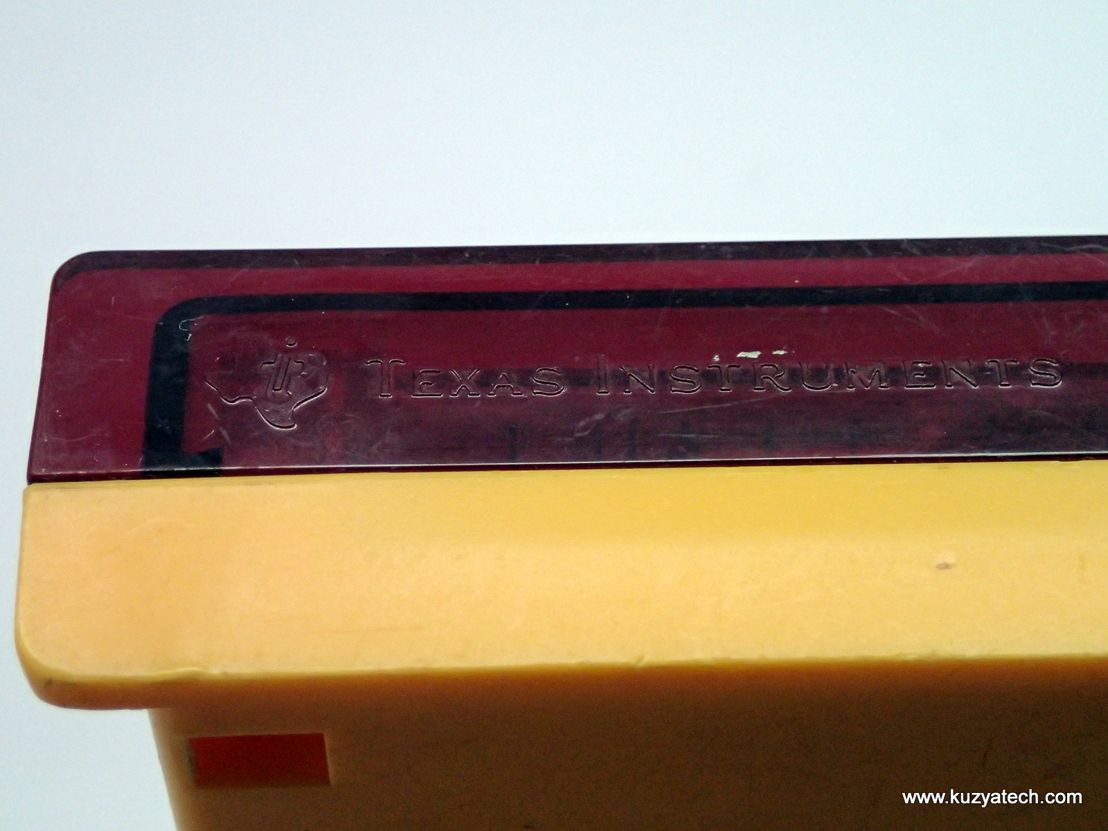
Today’s vintage entry is rather cute:
Introduction
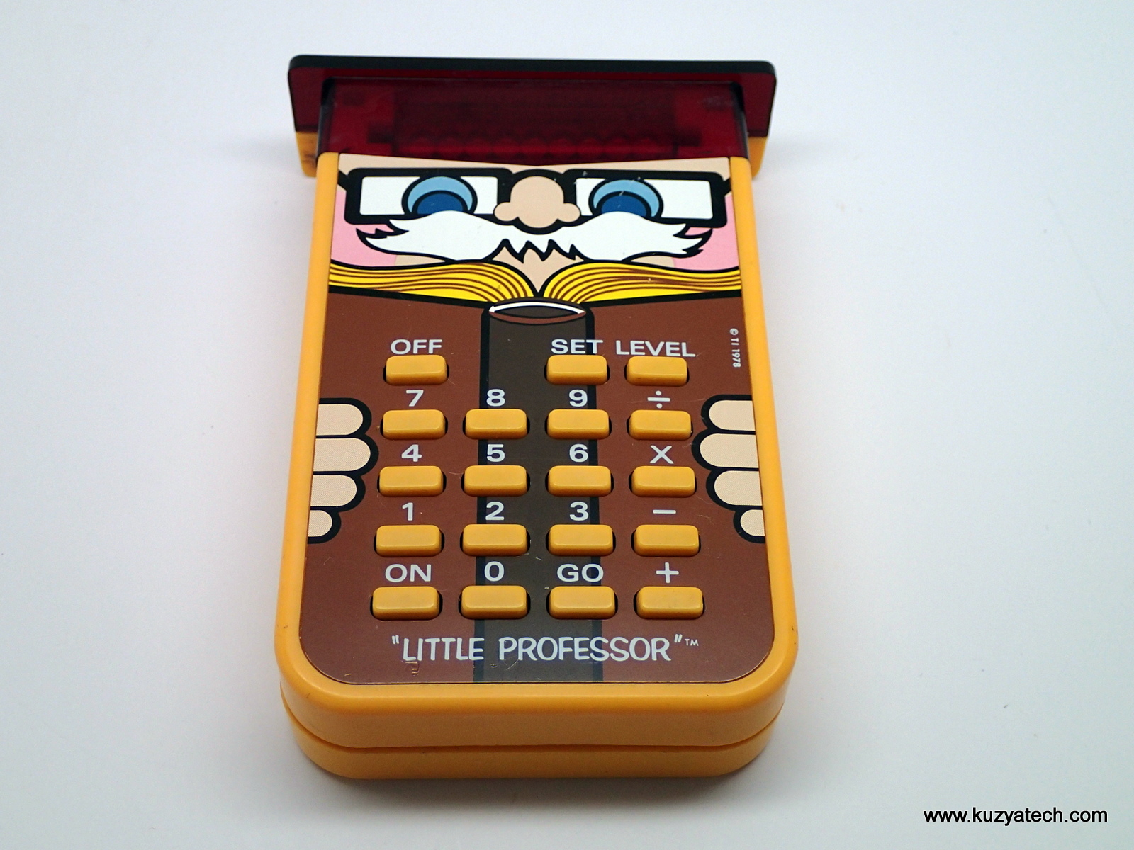
This thing was sold for parts and repair since the seller did not think it was working. As it turned out, everything worked just fine, but not in an expected way. This is not your typical calculator, but rather a teaching one. Here is a short video showing how it works.
Apologies for slow response time on my end- took a bit of time to remember how to do arithmetic in my head! After turning it on, you select operation being taught (addition/multiplication/division or subtraction) by pressing an appropriate key, then Set. You then cycle through difficulty levels by pressing Level key. Pressing Go starts the session. A problem is displayed on the screen (say 23+65=). When you enter correct answer, things progress to the next item. Otherwise you get EEE to indicate wrong answer. In my short play with it I found it pretty addictive and refreshingly contained- no Twitter, or Facebook in it to distract me with.
Teardown (mechanical):
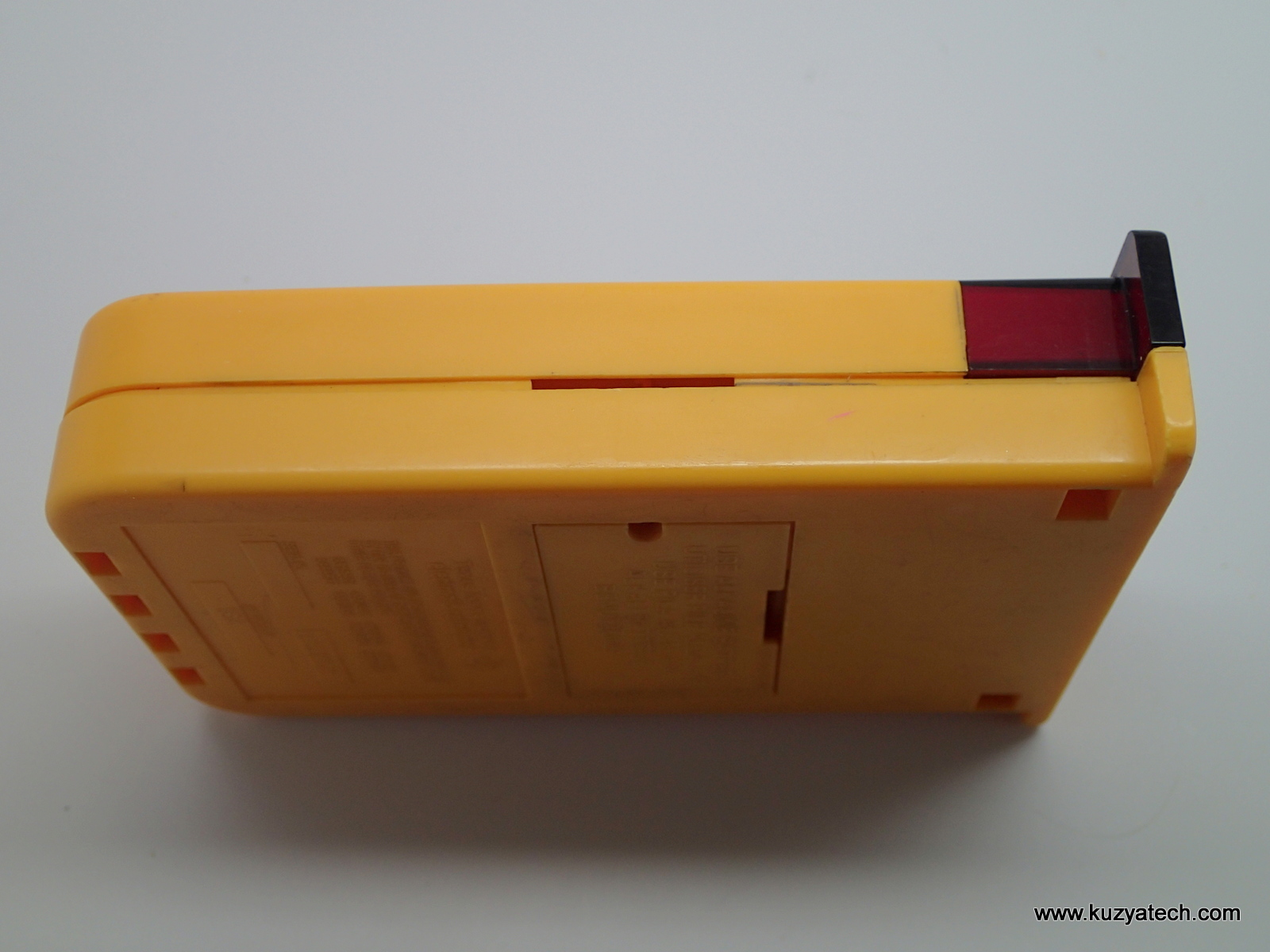
The case is held together by a series of clips, which being old and fragile, refused to cooperate and ended up broken: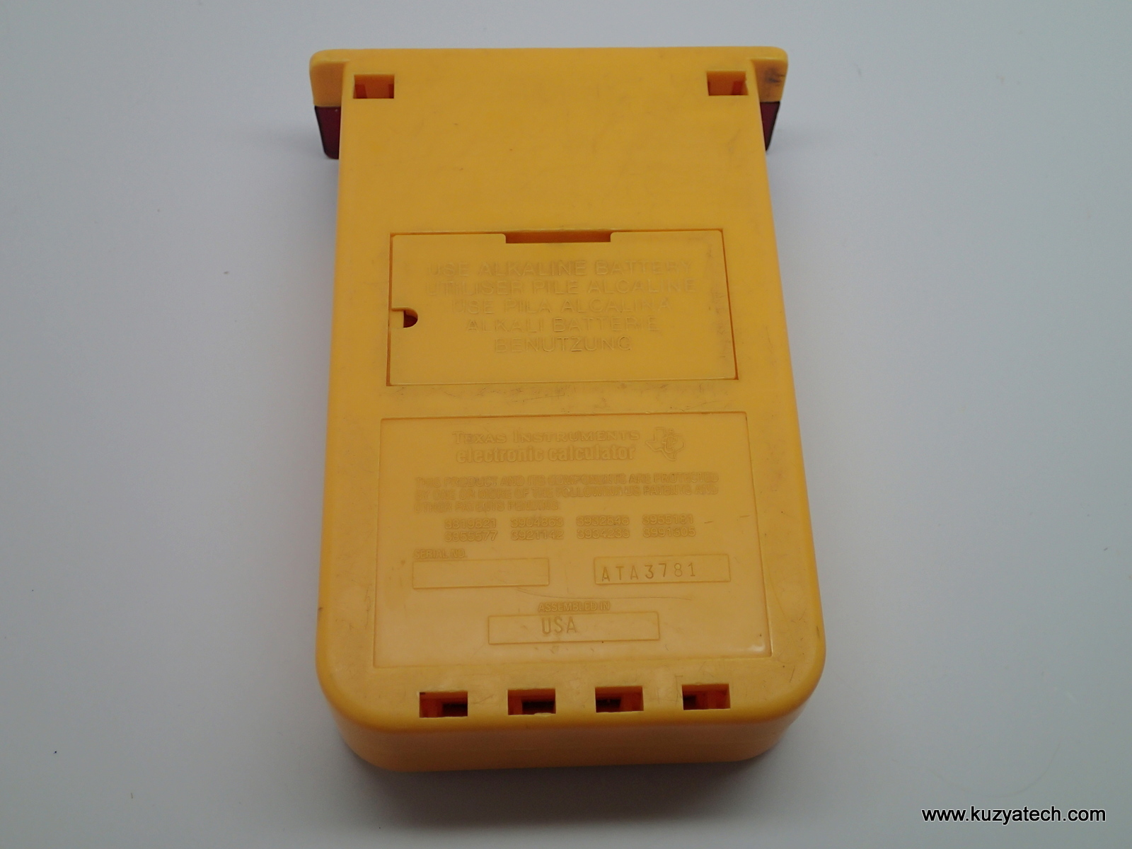
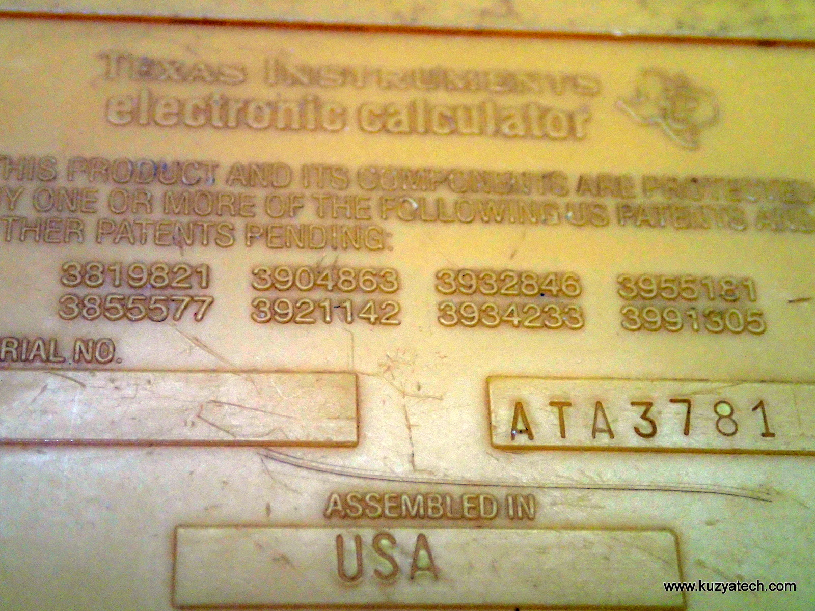
SN ATA3781 – made in 1981?
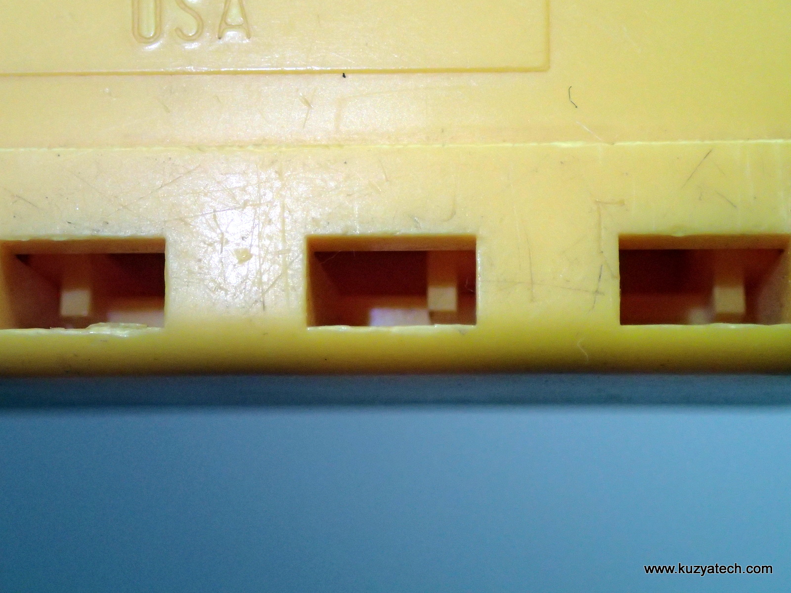
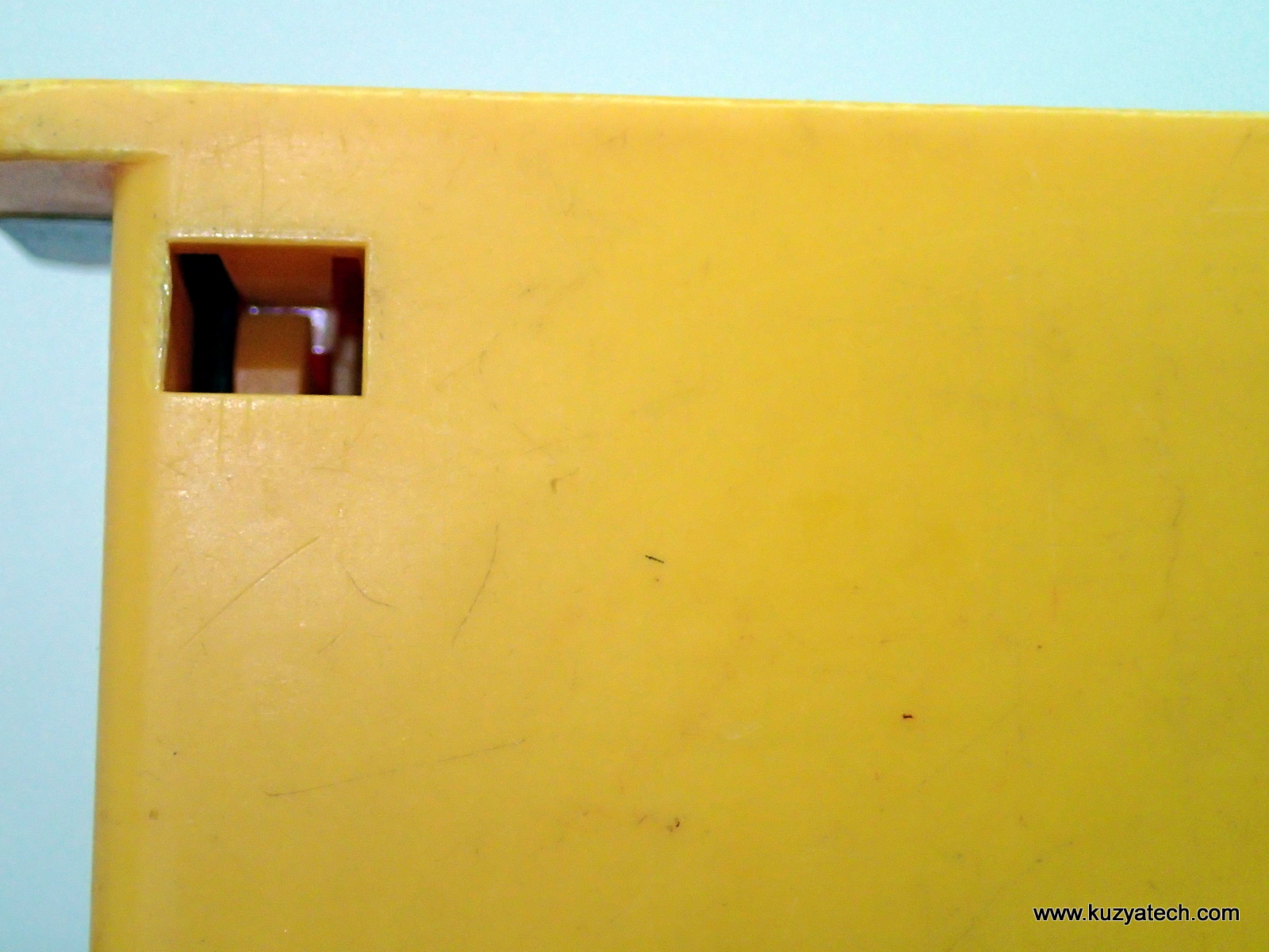
Interesting side slot
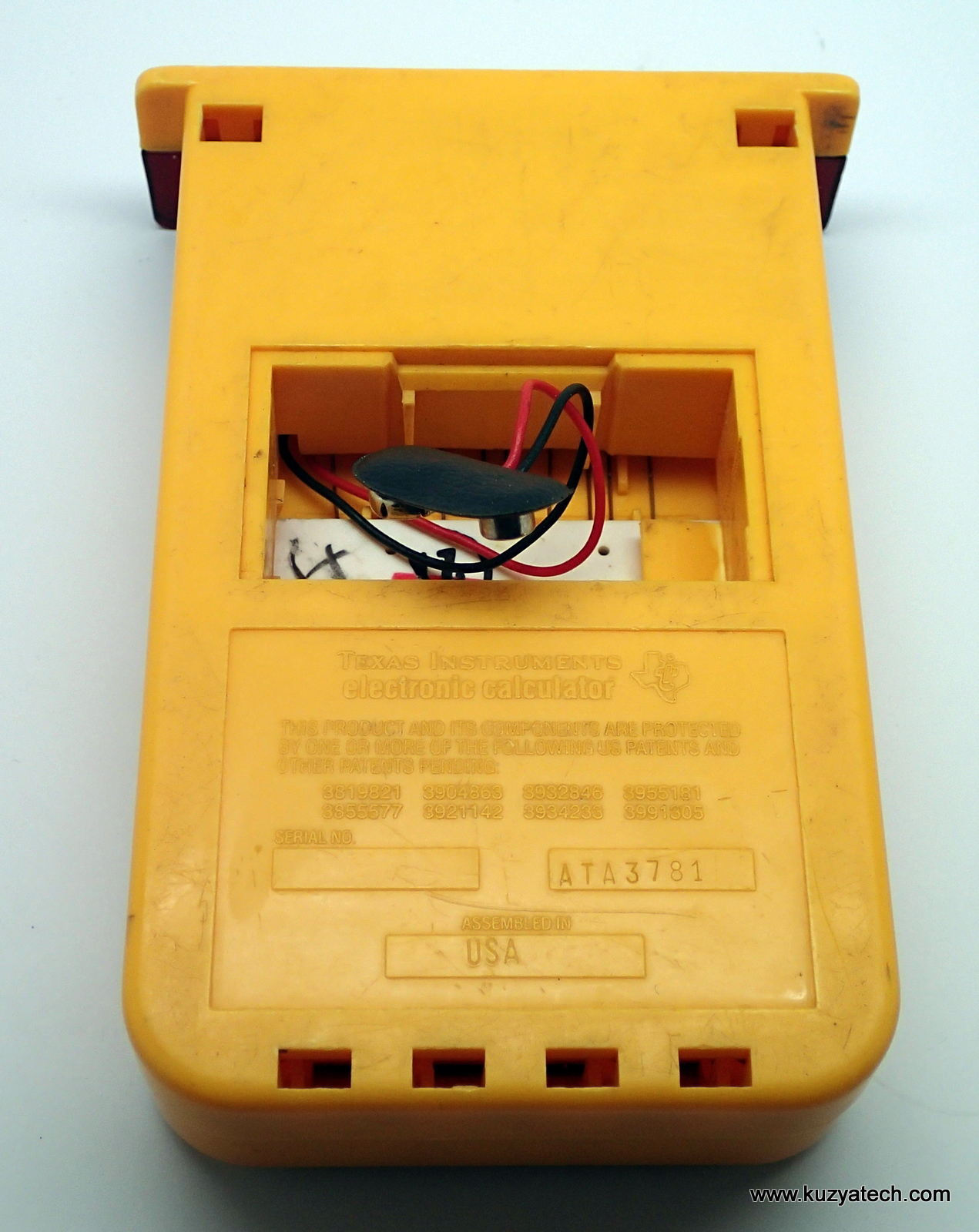
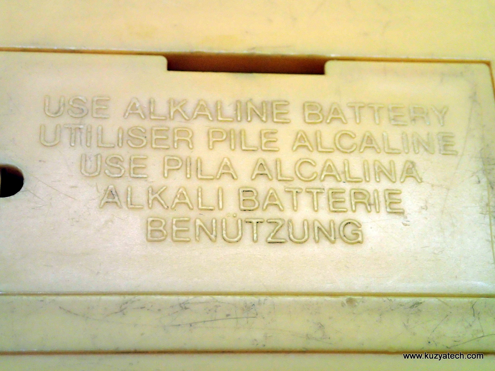
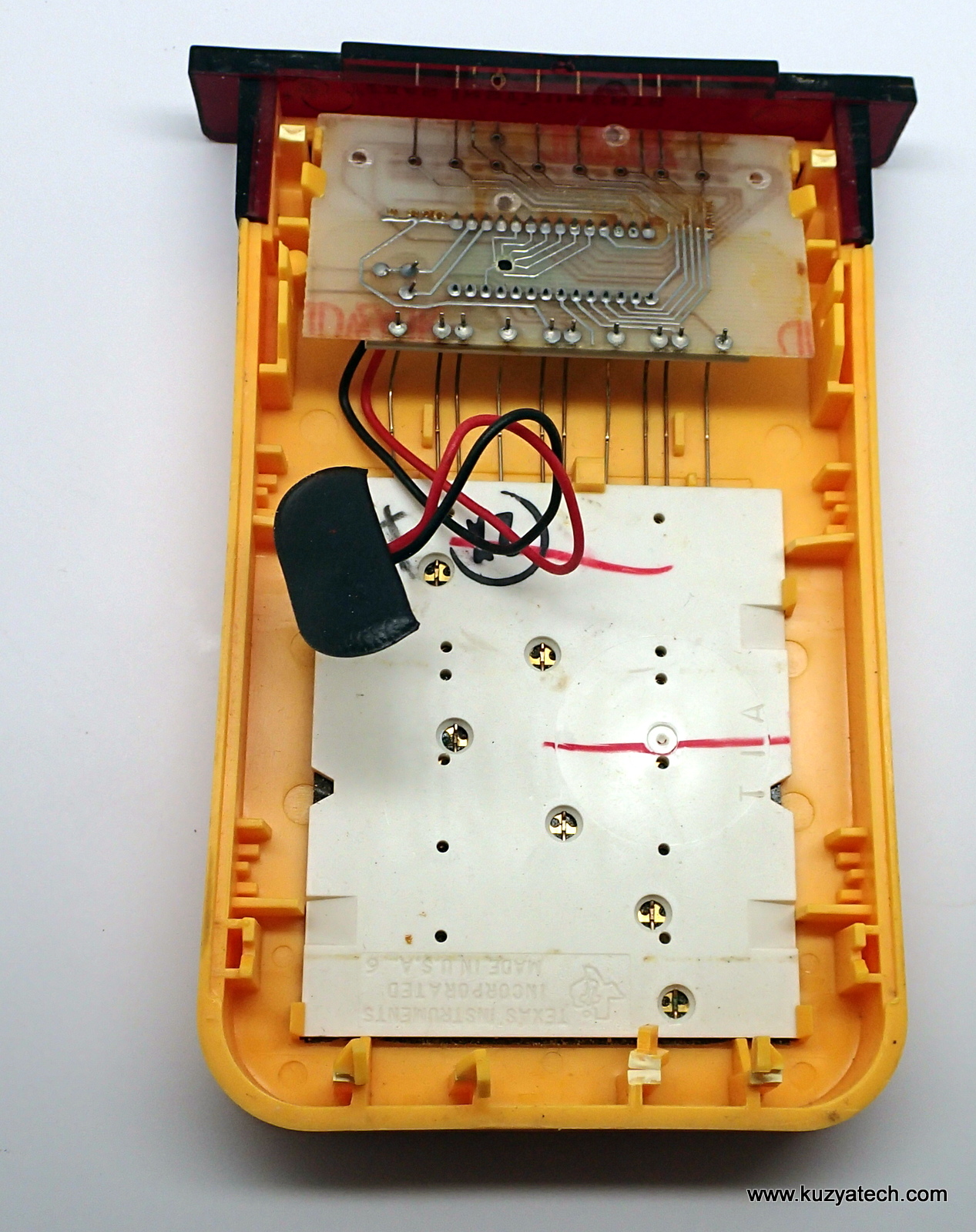
9V battery compartment
The design uses no fasteners as such- the case and PCB are all clipped together. The display lens is held by heat staking.
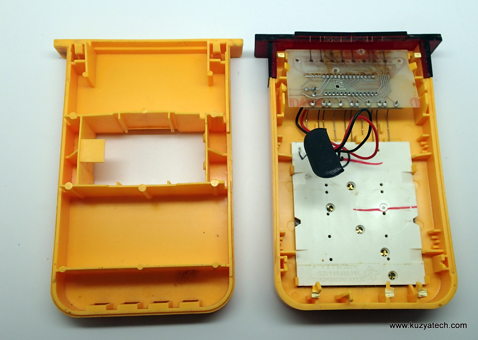
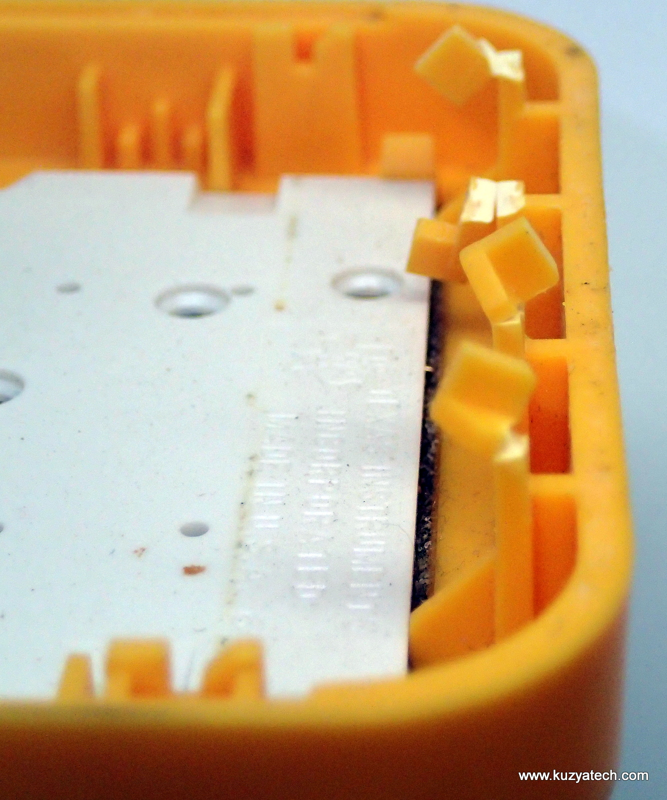
Collateral damage to the clips

Back of the keypad.
Teardown (electronics)
Not much there!
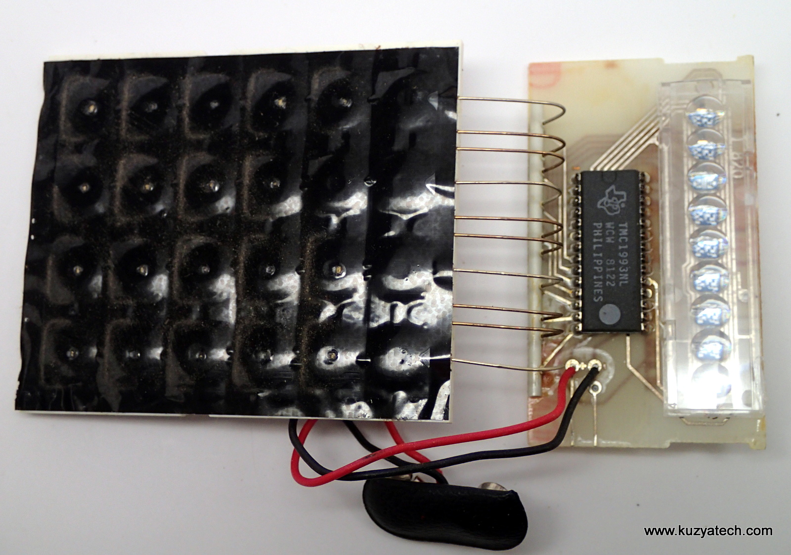
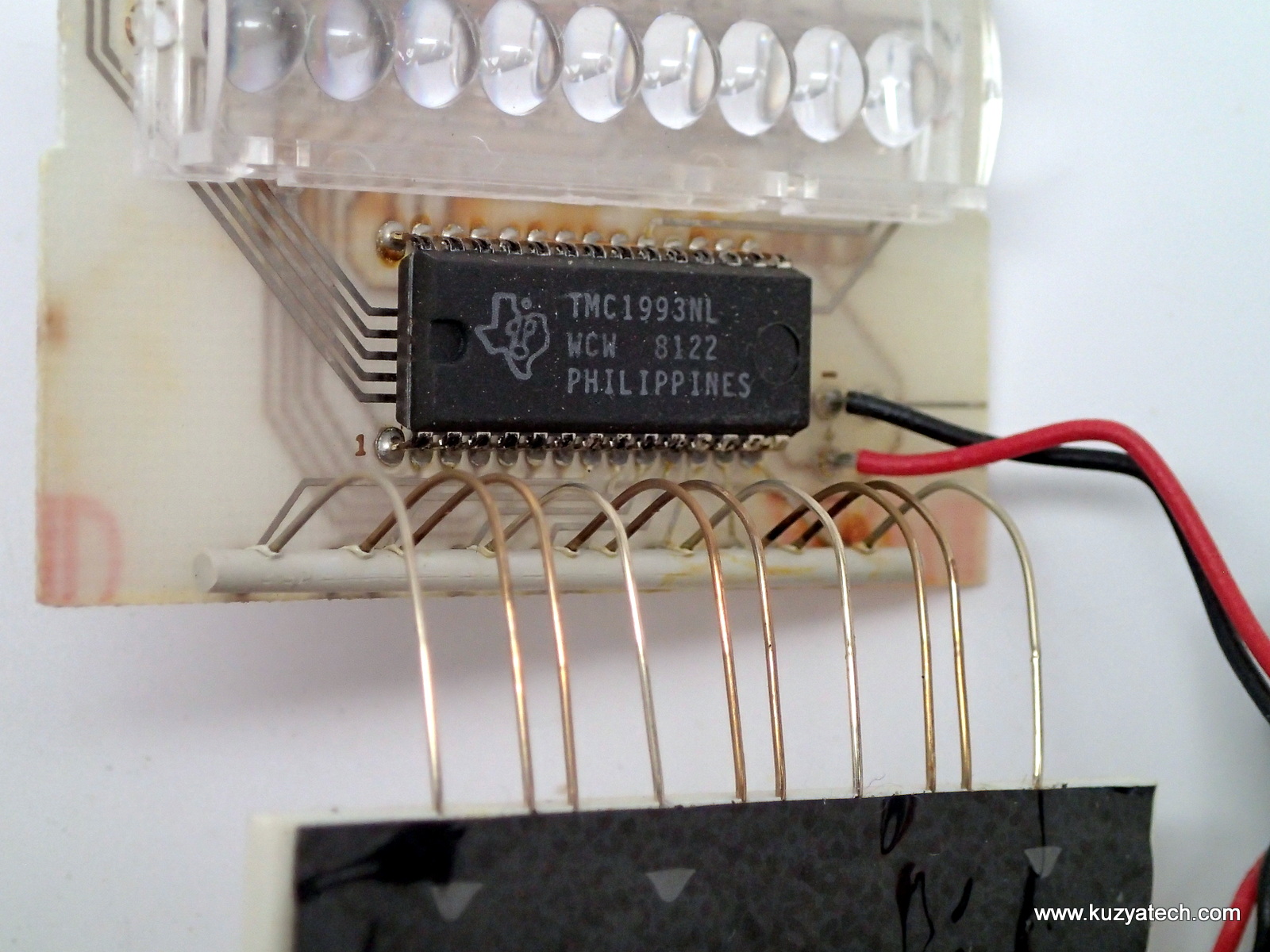
Inside we see a genuine single chip design- power in, multiplexed keypad and display out.
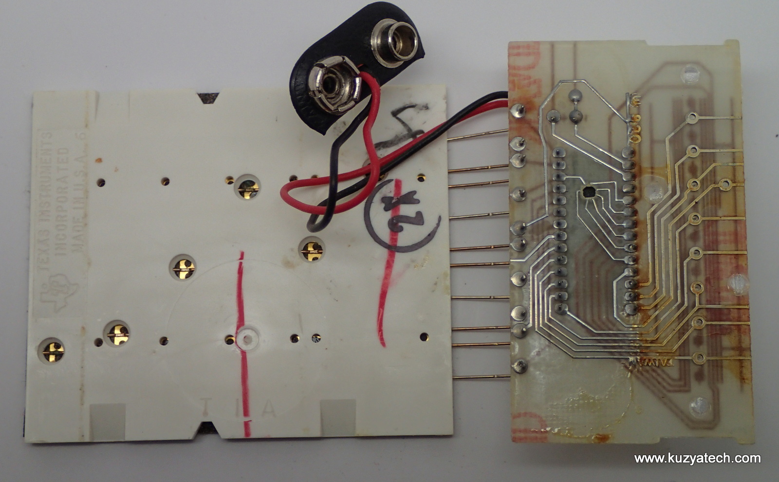
Oddly enough not a single cap is present. Also, what’s up with that hole that 7 traces “used” to go to? They all seem to be LED signals, so some external memory is not very likely.
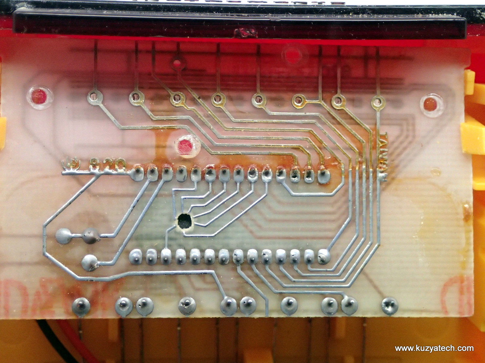
I wonder what the hole in the middle is for?
More details on the keypad- if we peel a corner of the black plastic, we can see how the buttons are made. Interestingly enough, the domes are not individual but arranged in strips across the keypad (rows). That’s how they get away with connecting to each one in a single point via a contact weld.The domes in turn touch the column scan wires when pressed. No PCB needed.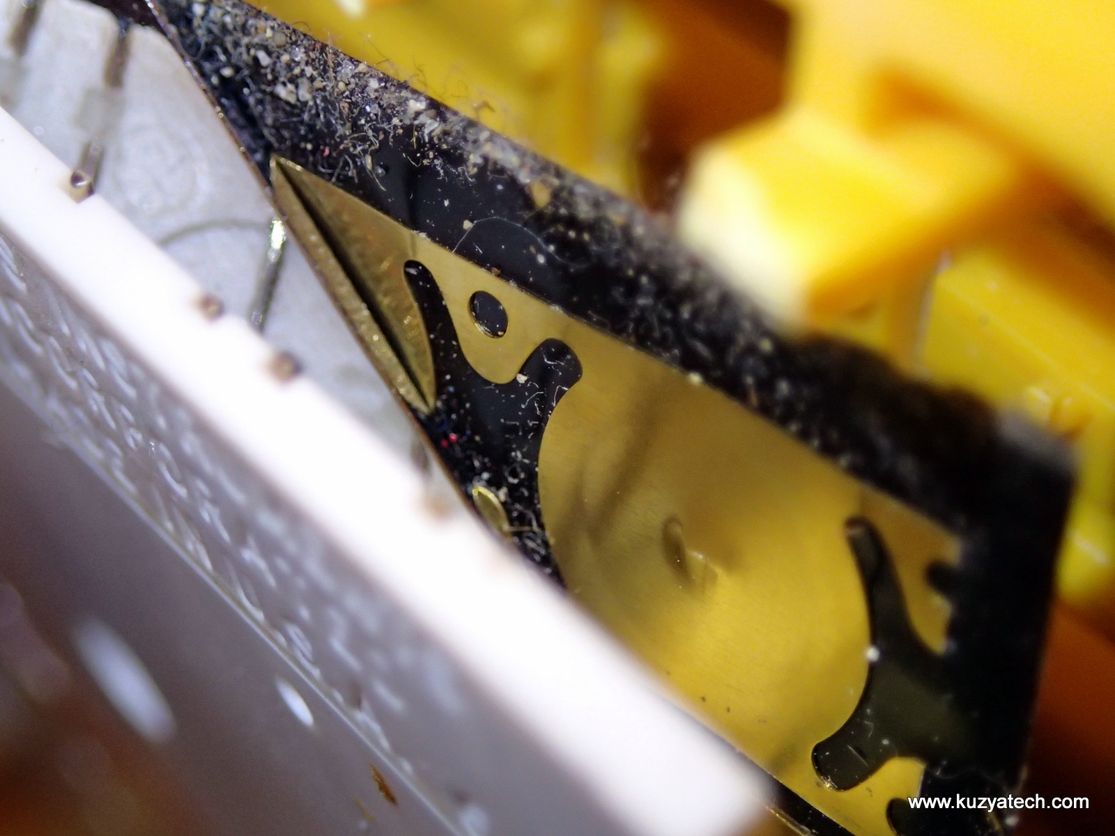
Not quite sure how the vertical wires are held in there- could be just recessed channels and sticky label over them. 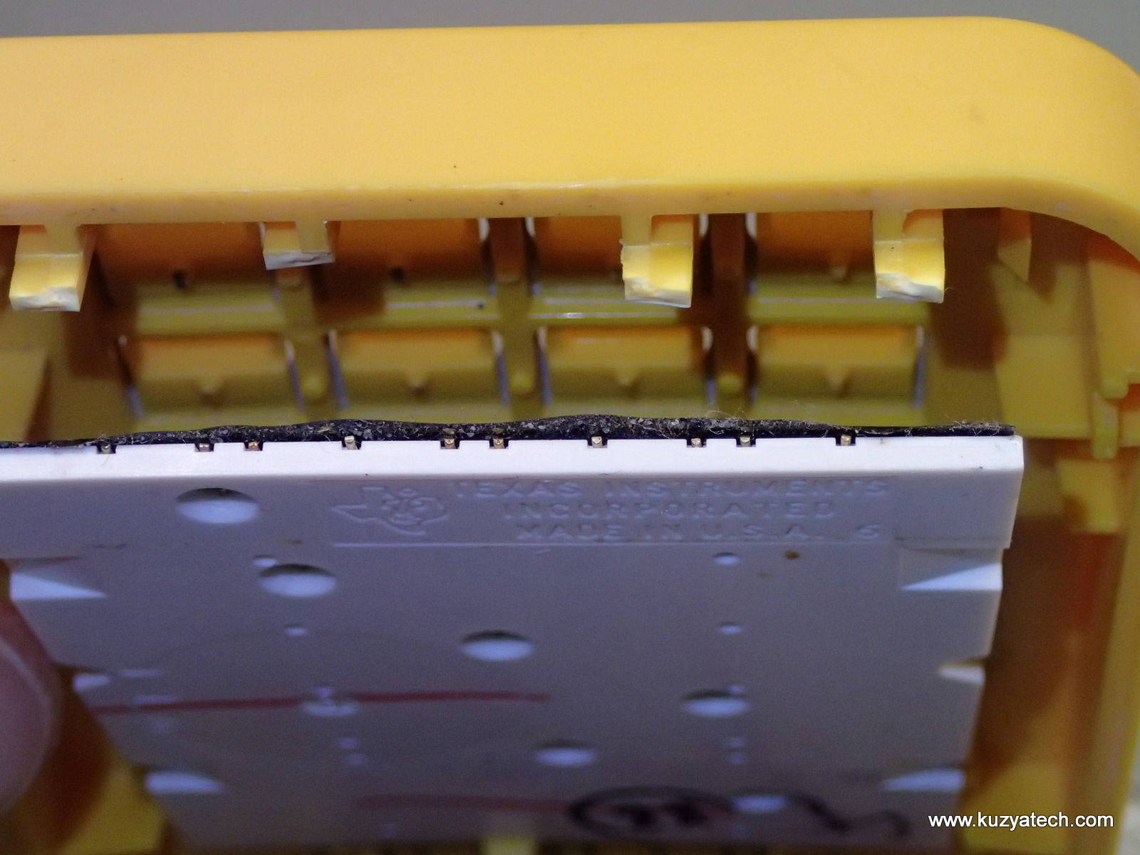
Some macro shots of the weld points. Each keypad strips gets one wire connected.
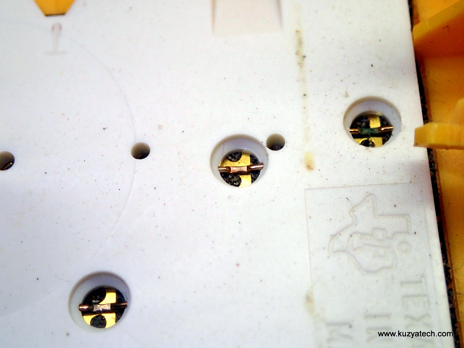
Seems to be some type of welded connection
Note an interesting way keypad wires are held in place- with a strip of plastic they got melted into:
Strain relief?
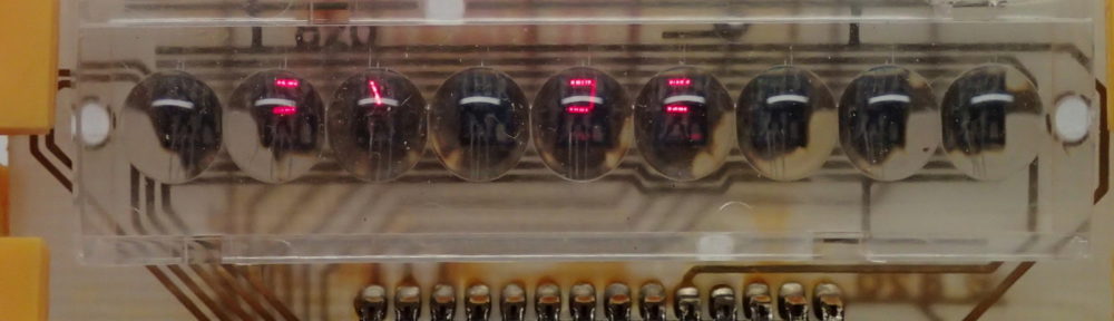
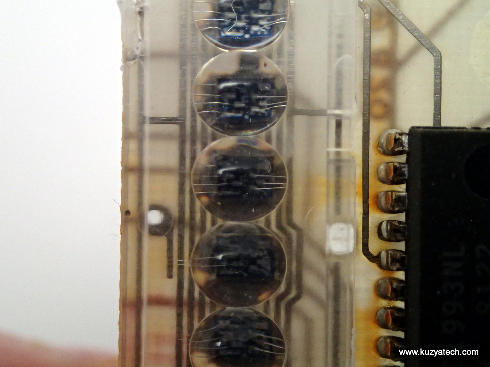
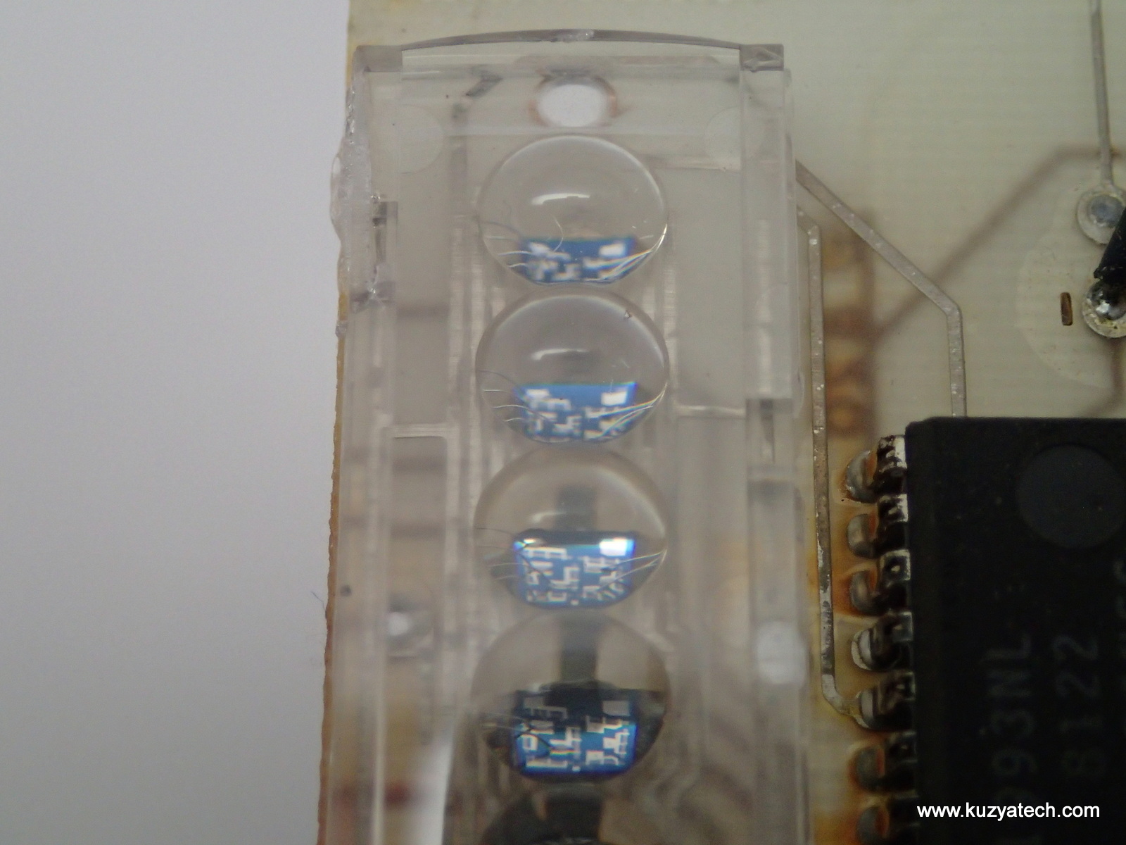
And now on to the bubble display- named that way for the lenses placed over the tiny LED segments:
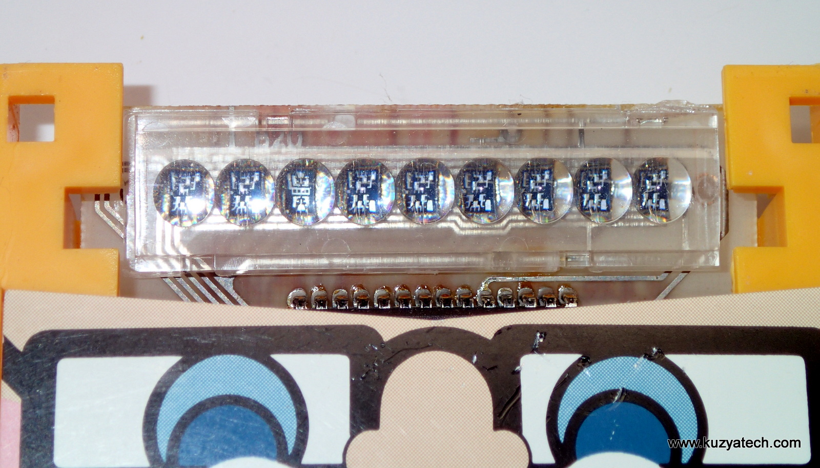
It appears the display is actually made of discrete segmented LED dies, wire-bonded to the board:
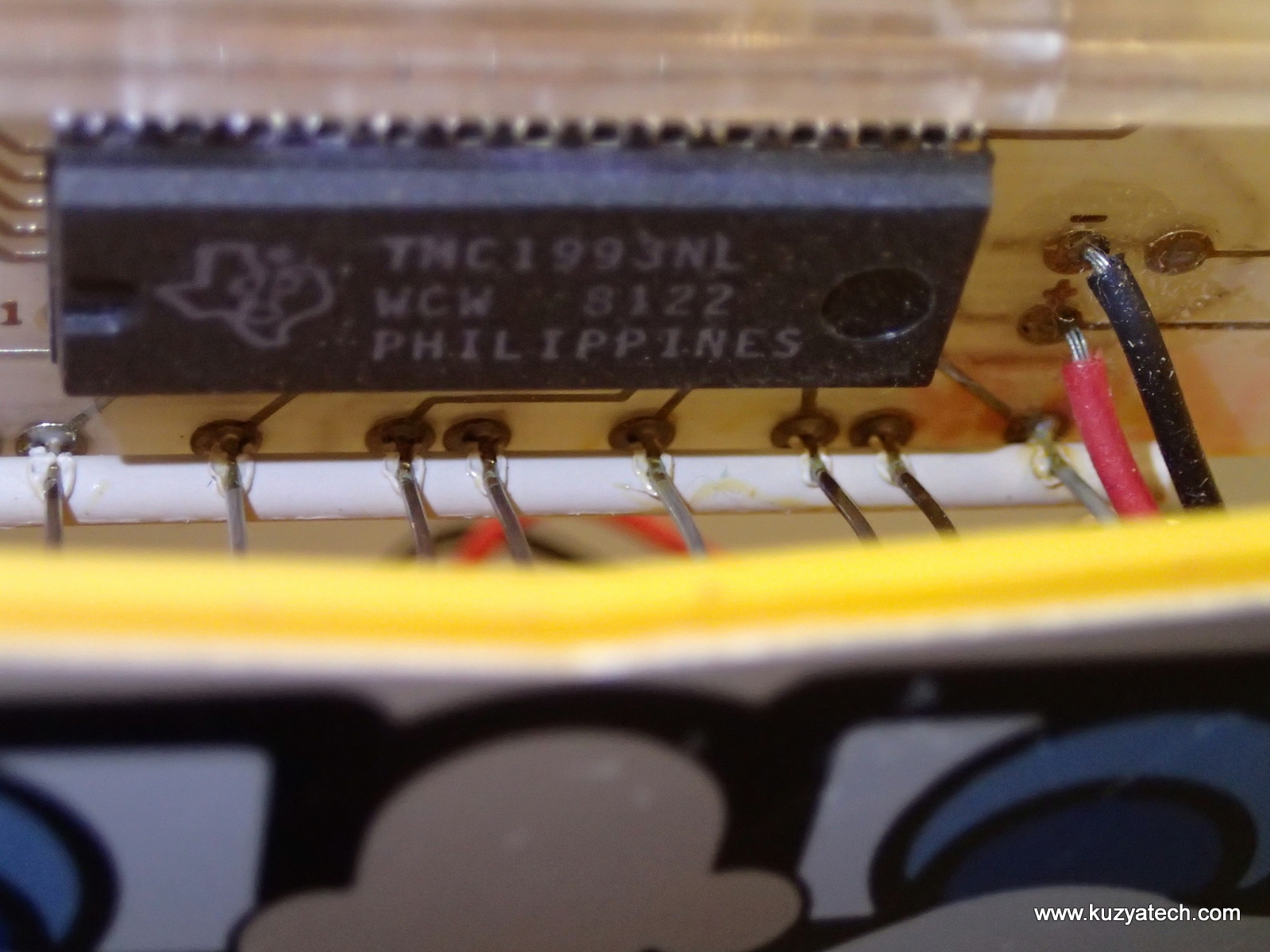
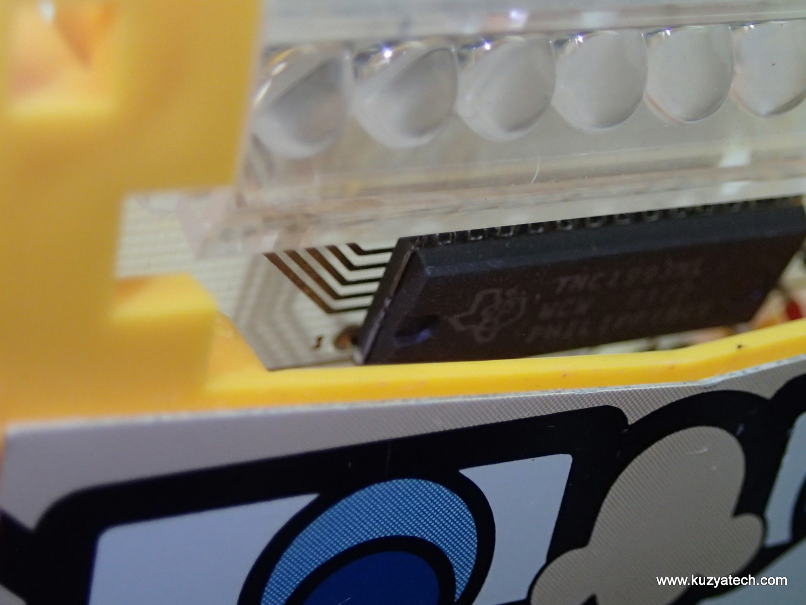
And here is the chip driving it all- a TI TMC1993NL (aka TI TMS1990) in DIP-28 package made on week 22 1981. Very impressive how much integration they were able to achieve, considering there are no other parts, even passives around. According to Datamath.org, the specs of the processor are: 4bits,1024×8 ROM, 64×4 RAM, 12 fixed and 31 programmable instructions, direct LED driver
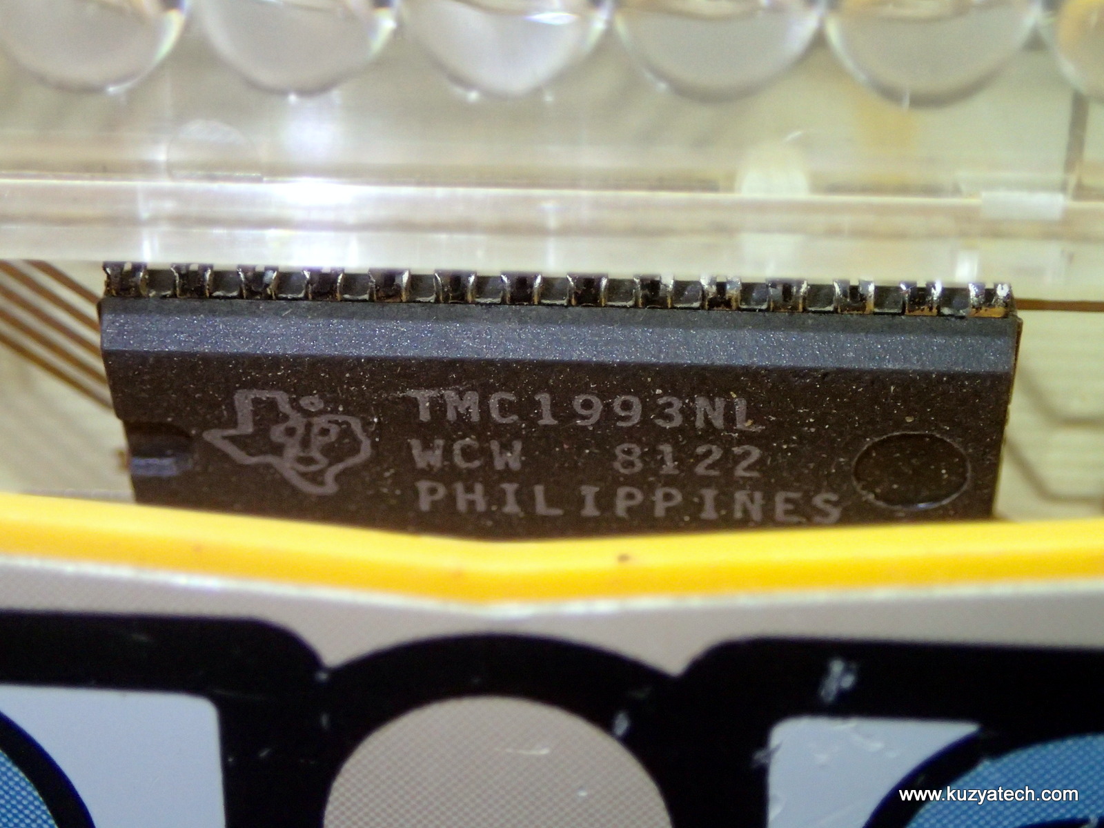
TMC1993NL with 8122 datecode
Let’s turn it on:
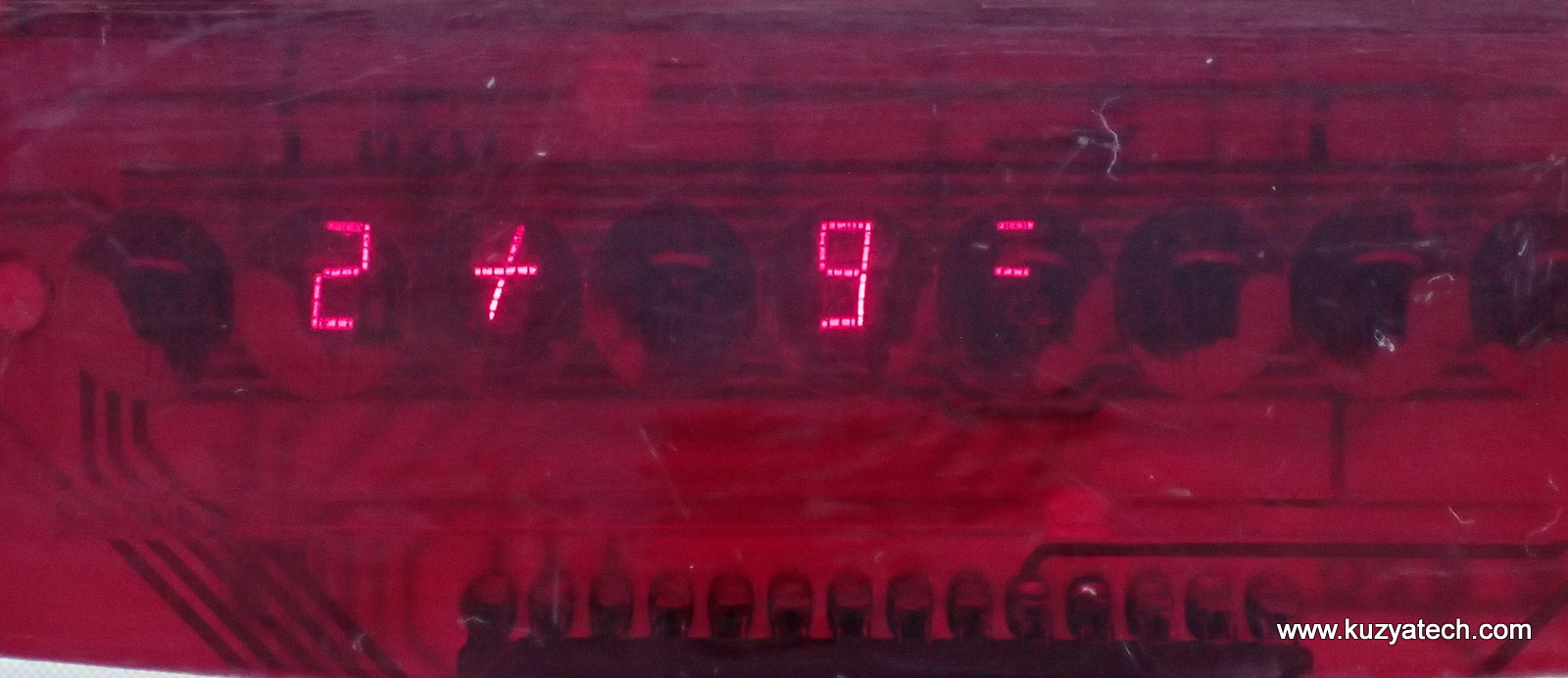

A bit at an angle, so some of the magnification effect is gone
Power consumption:
The design is surprisingly low power for its age. I measured 19uA in the OFF state,
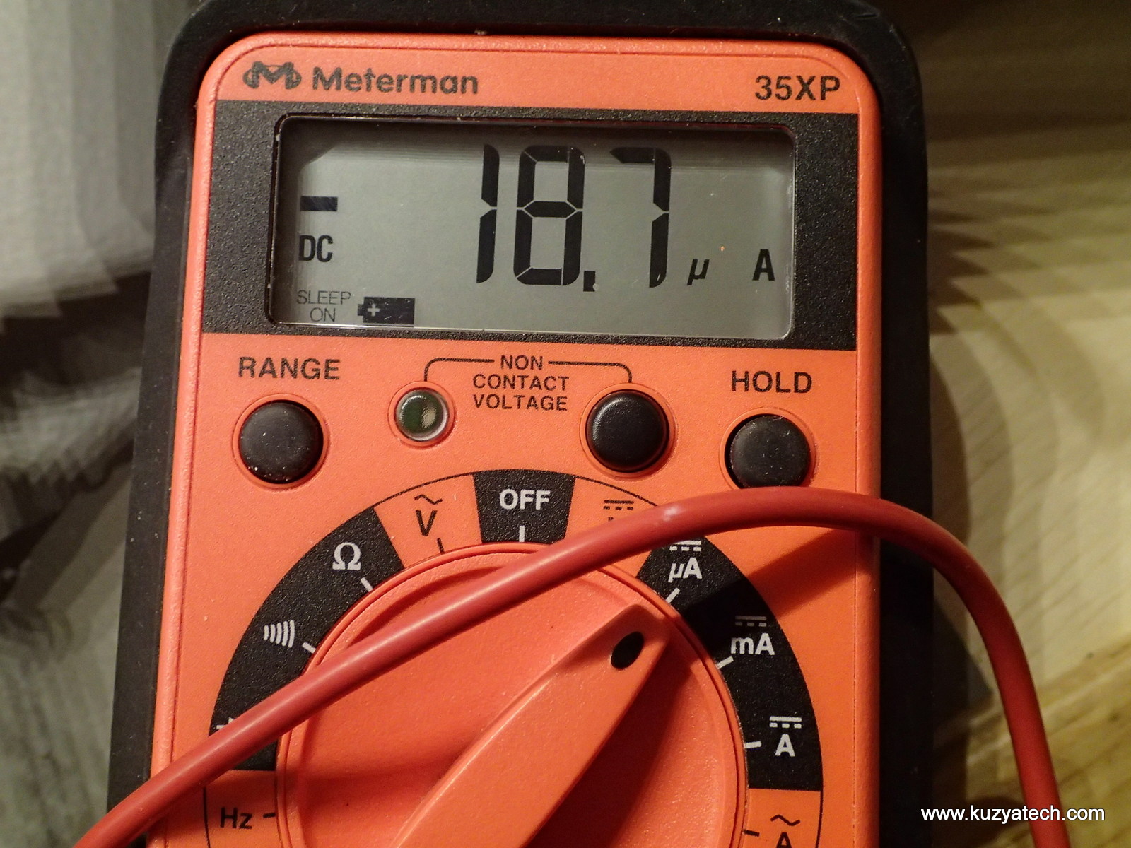
Sleep current
around 12mA in idle,
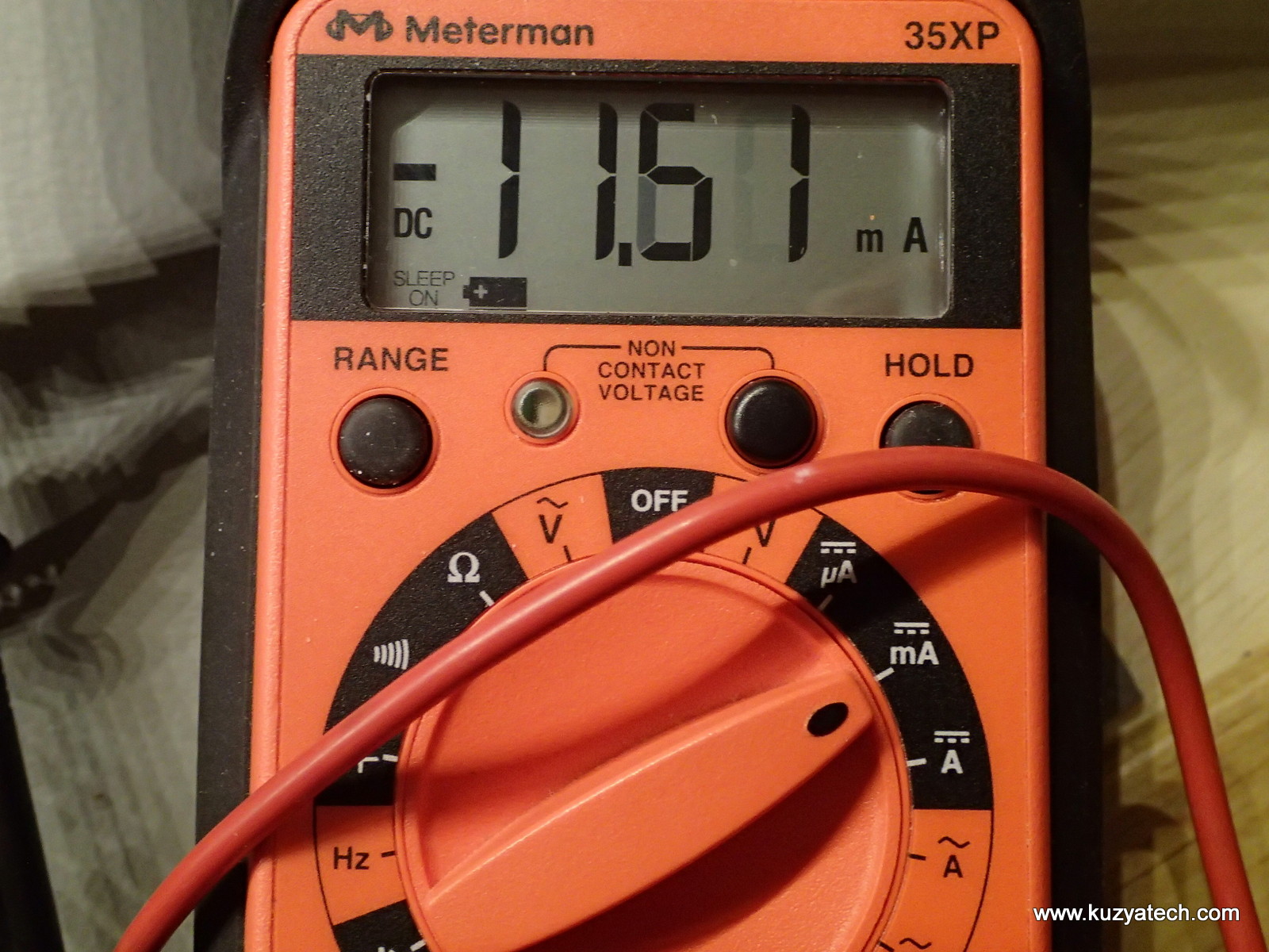
Idle mode
and 22mA under full load
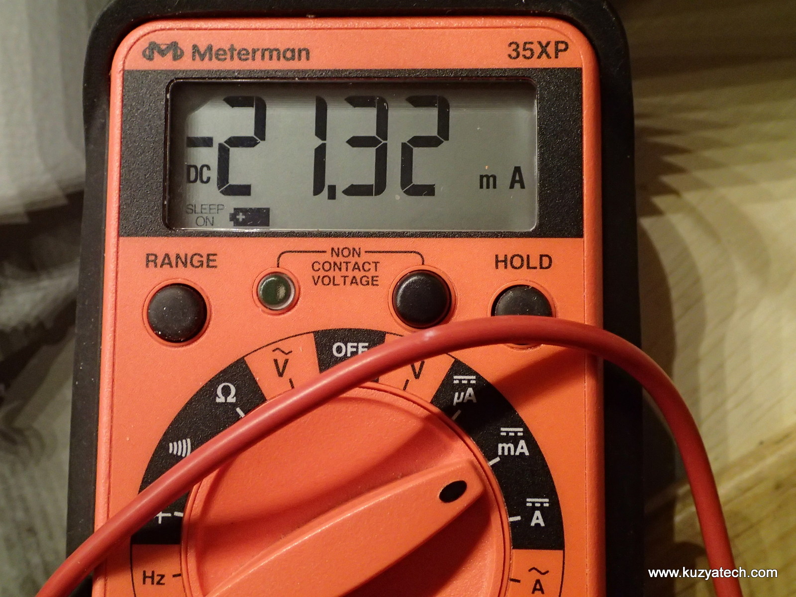
Full load
Conclusion
Very neat design, optimized for easy assembly. Everything snaps together, wiring is minimal and so is the power consumption. And to top it off, it appear MAME project supports emulating this thing with the proper ROM (which are floating around the net).
Interesting post. I think that the hole in the middle breaks a short of all converging traces, short of selftest after assembly. You may try shorting again and see what happens
Wow I remember I used to have one of these when I was a kid.