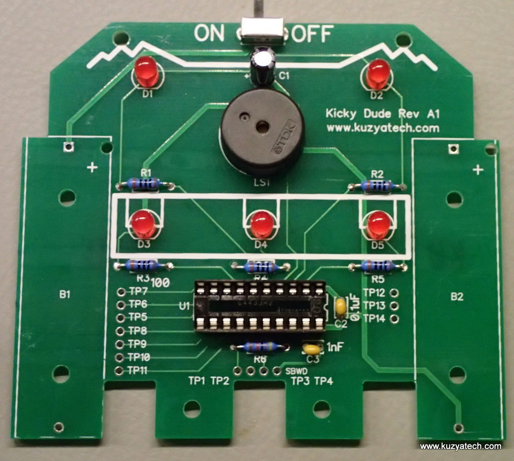
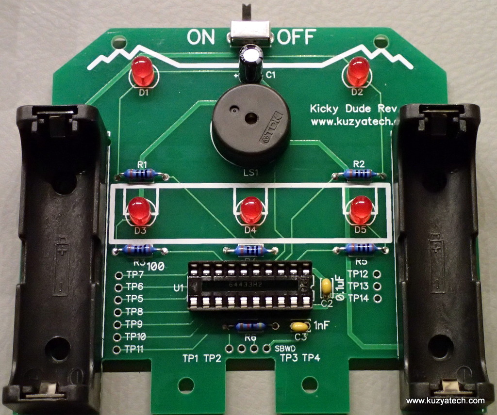
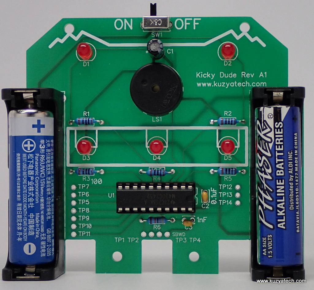
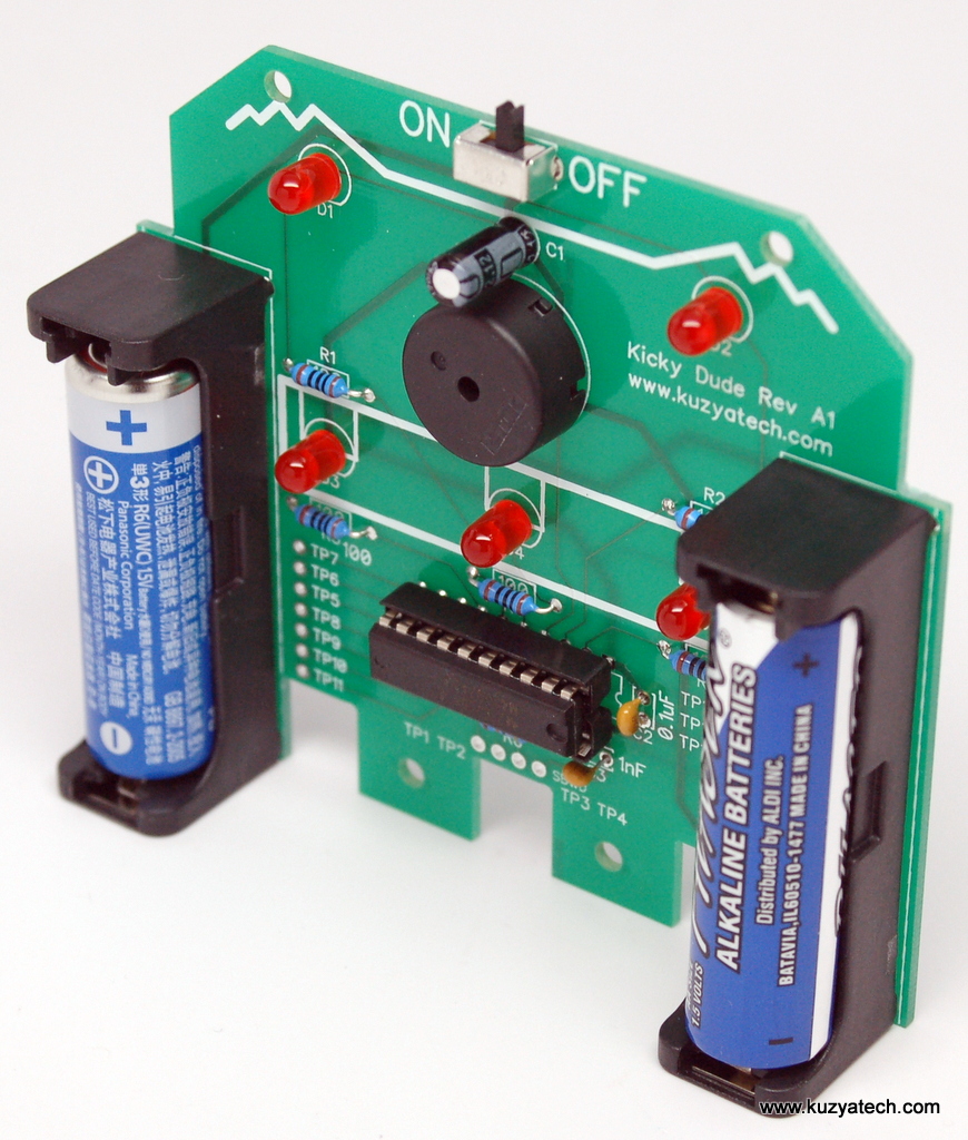
This came out from a need to scratch a personal itch. We needed a prompter to give signals when and where to kick the target for our Taekwondo practice. So we made a little dude who stands and beeps/blinks semi-randomly to show kick location. It’s a perfect kit to put together with a child as there are few parts and they are large and easy to solder. There are 59 total solder joints to make. The processor is socketed and can be inserted once all the assembly is done. This is an open source hardware design under CC BY SA license. You get a blank PCB and all parts needed, including preprogrammed MSP430G microcontroller. Uses two AA batteries and should run for a very long time- tested down to 1.8V and still operating.
Source code is available so you can tweak timing and behavior as desired. The processor (MSP430G2452IN20) can be reprogrammed in-circuit using SpyByWire or by taking it out and plugging into TI Launchpad. All unused pins and SBWD signals are brought out to test points on a 0.1″ grid for ease of hackability.
Board size is 83mm tall x 95mm wide.
Available as a kit on Tindie. Schematic is here.
Build instructions.
Step1
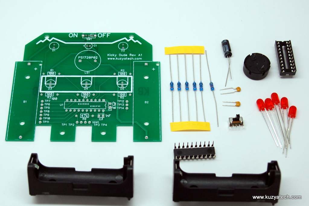
Check that you’ve received all the parts pictured:
Step2
Form resistor legs, by bending the leads with pliers 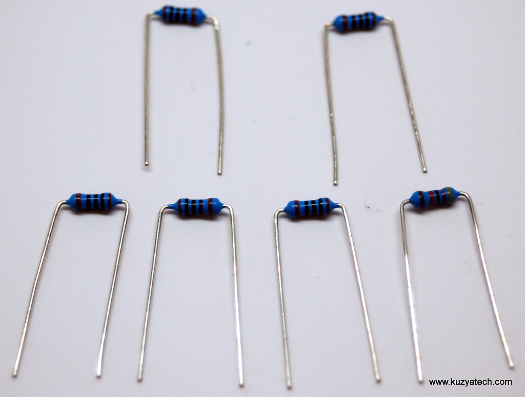
Step3
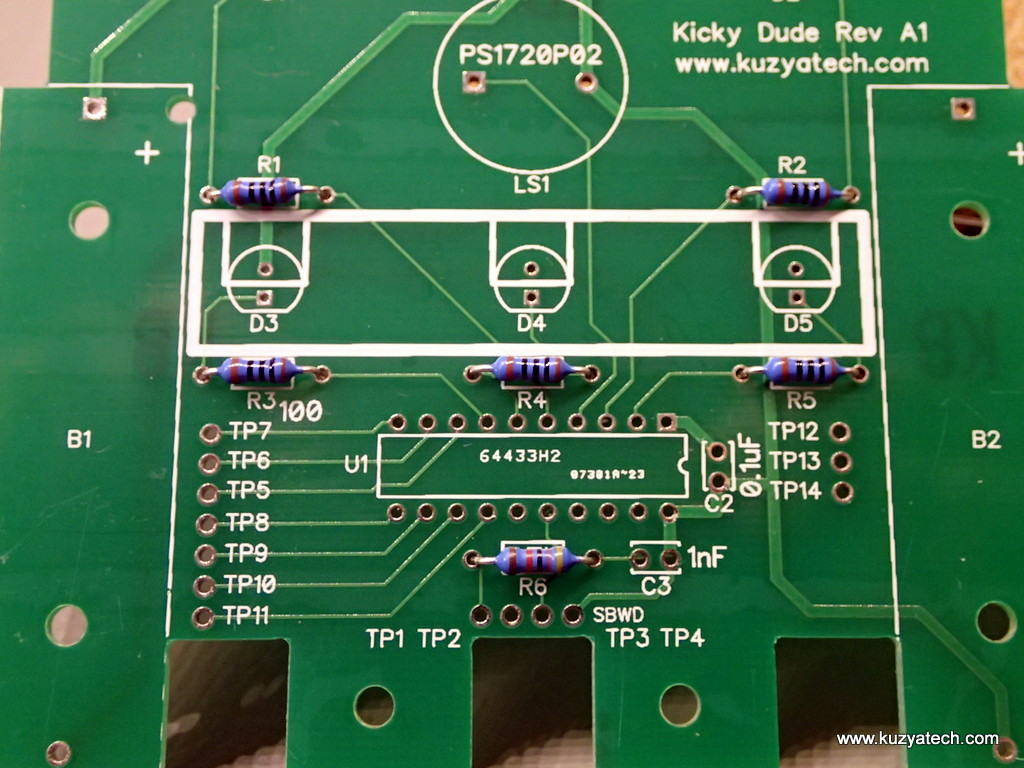
Install resistors in their spots. Note that five of them are identical 100 Ohm (R1-R5) and R6 is different (47k). As you put them in, bend the leads to help hold them in place.
Next, solder them in.
Step4
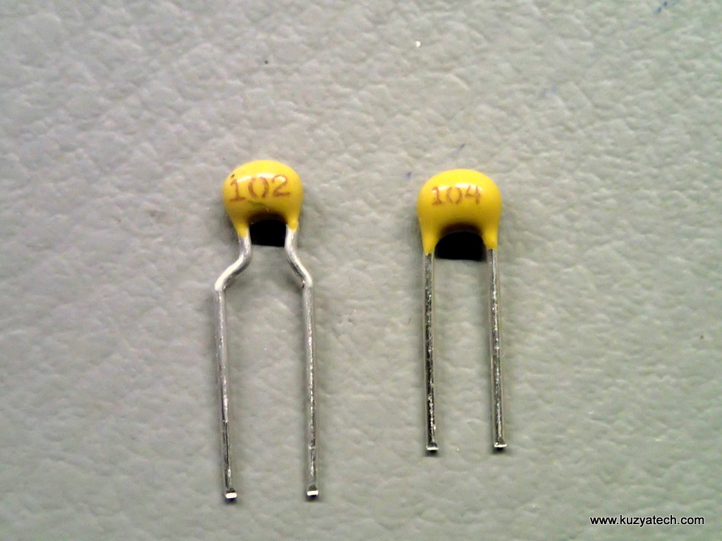
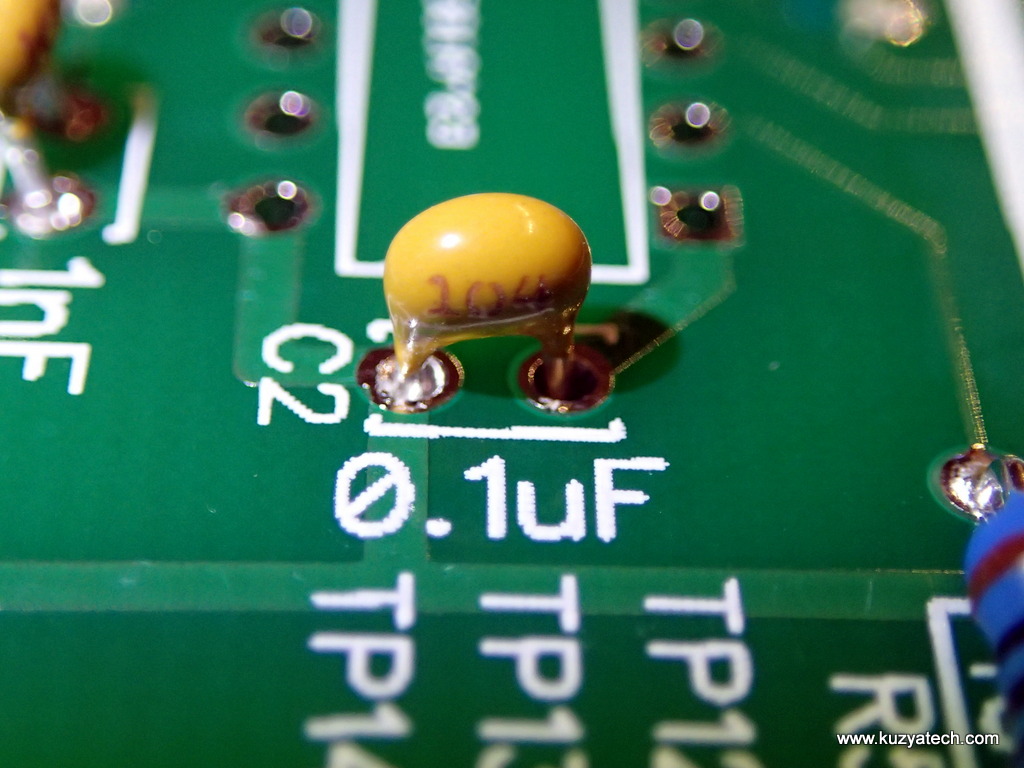
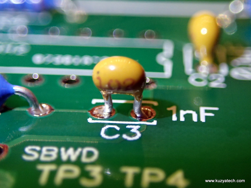
Prepare capacitors C2 and C3 . You may need to bend the leads a bit to fit the 0.1″ spacing
Step5
Install and solder C2 and C3. 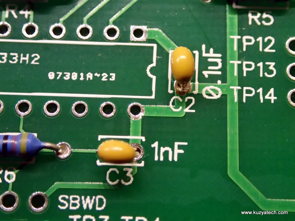
Step6
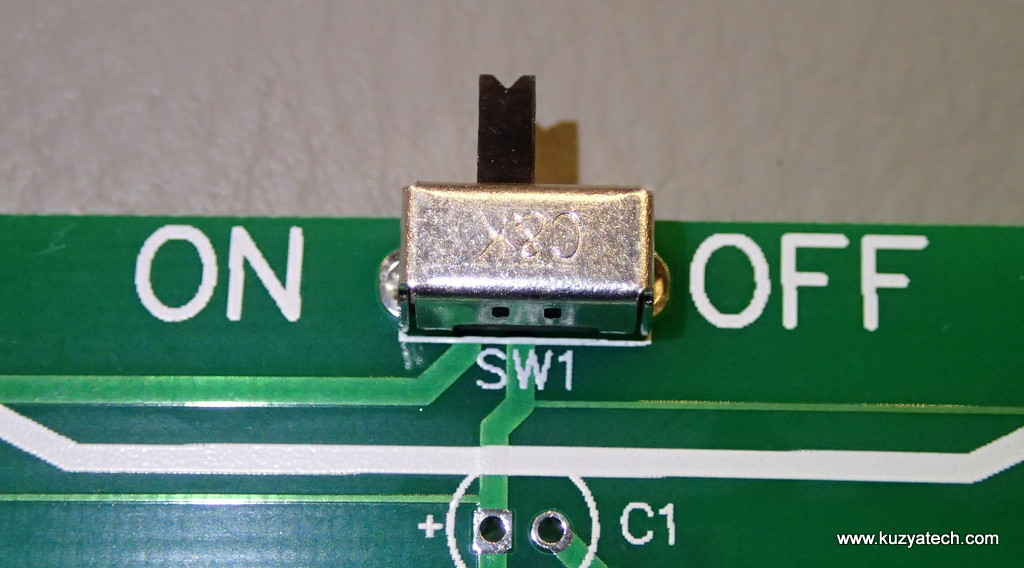
Install and solder power switch. Make sure all pins get soldered, including the support ones
Step7
Install piezzo buzzer LS1, It is non-polarized and can go in either way.
Step8
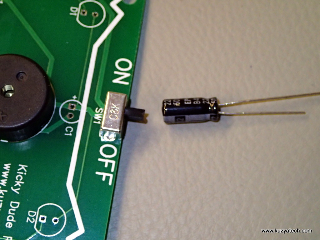
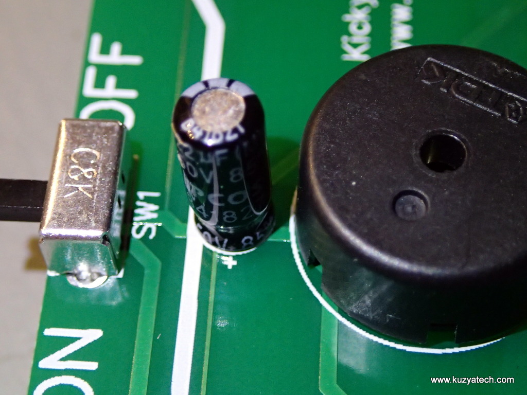
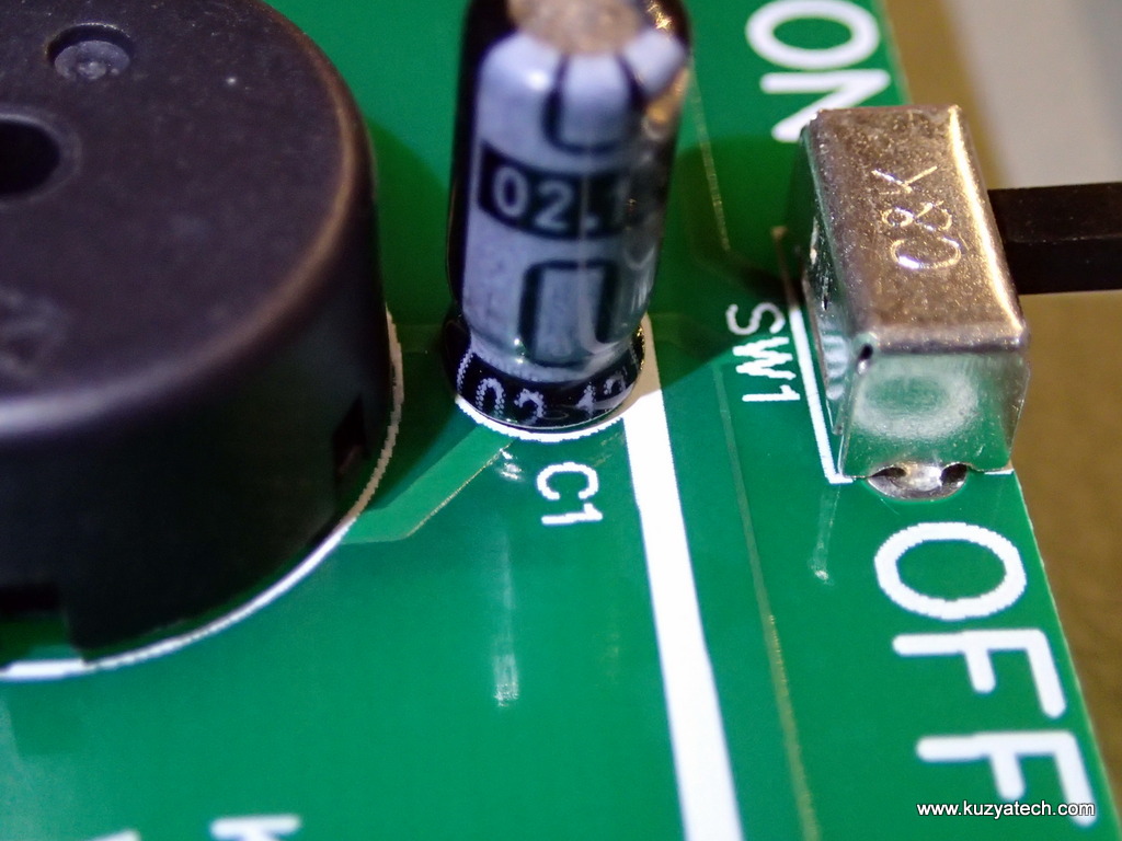
Install electrolytic capacitor C1. Note that the negative side is marked on the body and also with a shorter lead. Positive side is a square pad and marked on the board with a +
Step9
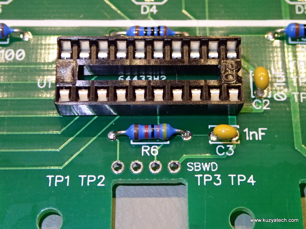
Install pin socket for the microcontroller. Make sure the notch on its body aligns with the notch on the silkscreen
Step10
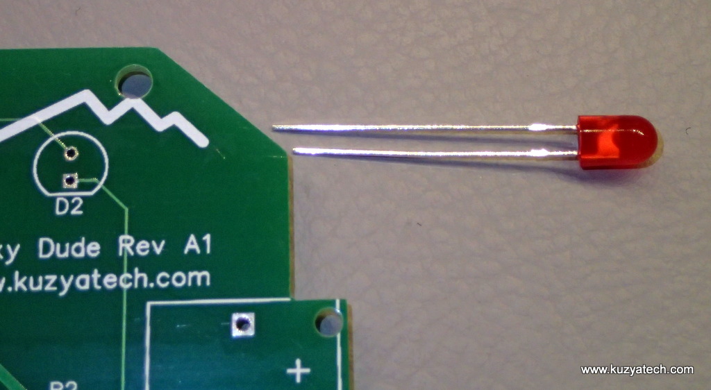
Install LEDs D1 -D5 . The shorter lead goes into the square pad:
Step11
Take a close look at the board and make sure all parts are in the correct places and soldered:
Step12
Install battery holders. They are keyed and will only go in one way (Plus side facing the top)
Step13
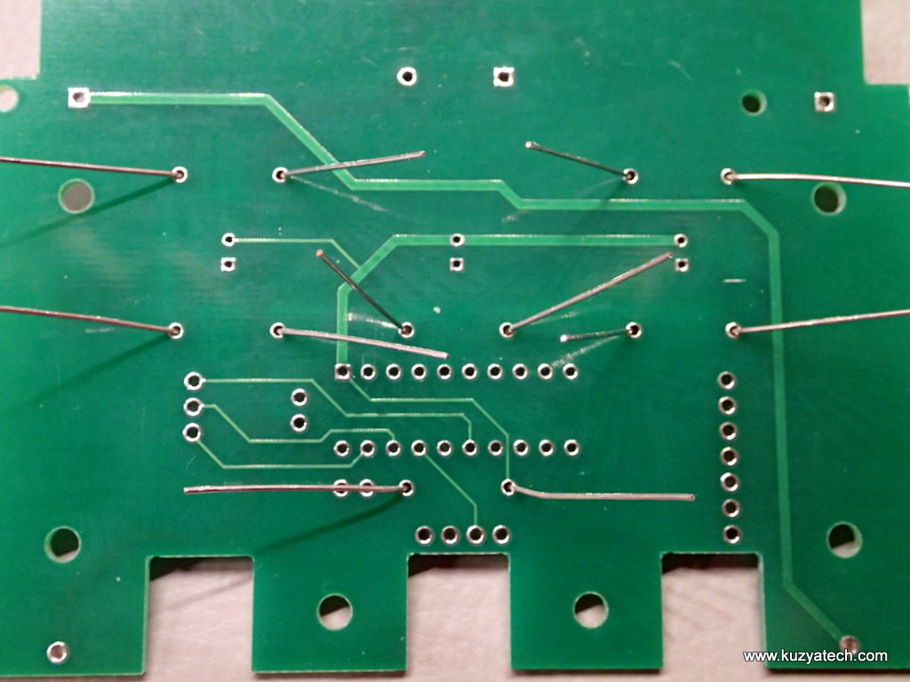
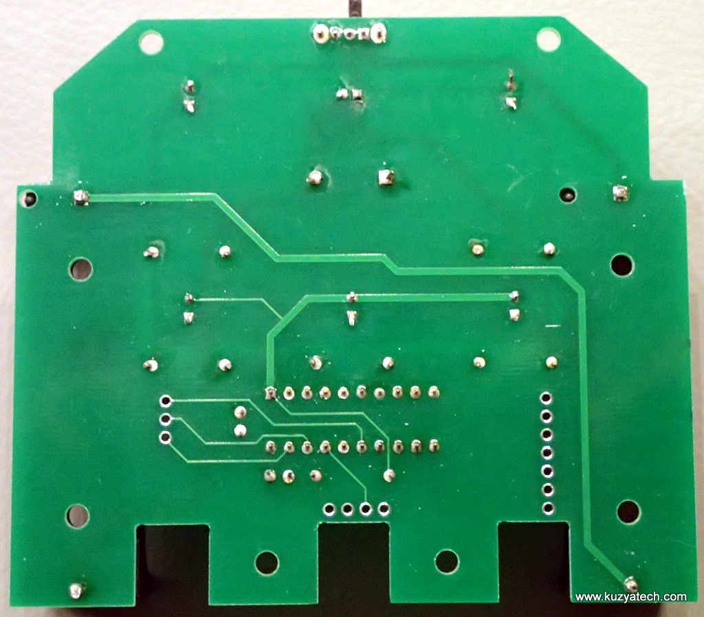
Flip the board over, trim any remaining leads and check that all solder joints are indeed soldered. The three rows of unused holes are testpoints and can be ignored
Step14
Install the preprogrammed microcontroller, making sure its oriented to match the notch on the silk and the socket. Put batteries in. Note that they will only fit one way
You are done. Flip the power switch and enjoy the random beeping and blinking goodness of the kit you just built.The battery holders are heavy and flat, so the Kicky Dude has no troubles standing on his own.
Here are a few more pictures of the assembled unit:

