Here is the BMS that came with my Headway LiFePO4 cells. After a few pictures it’ll be very clear why I felt really leery about entrusting my cells to its care.

Looks like this was a 13 channel design, with only 8 populated

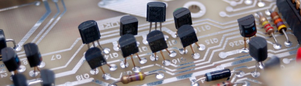
Board looks hand-build, looking at the solder joints

More awesome soldering, bodge resistors and a few wires fixing traces. Looks like a shippable product to me!

A better view on the bodge mods

Looks almost hand cut- just a sheet of aluminum, no fins to speak of
Overall feature set is pretty standard for any BMS. There is a balancing section (large blue power resistors and S8550 PNP transistors), controlled by some type of voltage monitors under the goop on the back, Over and Under voltage monitoring section, and series elements (IRF4310 and unmarked STM FETs) to disconnect charging and load whenever the limits are reached. There also appears to be a current protection feature, judging by sense resistors RX1 and RX2. Out of eight FETs, two are in the CHG- path and 6 are in the PACK- path) On the back there is a thermal fuse, which is a nice touch. (Probably the only nice touch on this board). Overall assembly quality and board quality is rather dismal, looking more like a prototype than a production version. I especially like the “bodge” resistors from Gate to Source. Apparently they did not make it into the design!
Thanks for the post. I’m looking forward to seeing your own LFP BMS when you finish it.
Did you ever make a Bms