Today’s teardown target is a retired carbon monoxide detector made by First Alert.

The general consensus is that these should be replaced around every five years or so to minimize the risk of sensor degradation getting in the way of detecting an actual event. So let’s take this thing apart and see what makes it tick.

March 2005 manufacturing date
The case is held in place by plastic latches and one screw:

A fairly tidy design

A huge piezoelectric horn

The design is fairly optimized for efficient manufacturing- the board simply slides out, together with the 9V battery contacts. Mains contacts slide out of sockets

Very clean- AC pins just plug into the board.

AC terminals

Boards assembly
And here is the carbon monoxide sensor itself. Made by Figaro Sensor company, model TGS2442

Figaro TGS2442 Carbon Monoxide sensor

Once the horn is desoldered, we can see the chips underneath. It is all Microchip all the way: PIC16C717 OTP microcontroller, Microchip 24C00 128 bit I2C EEPROM and a now-Microchip RE46C101E piezo horn driver. X1 is a 2MHz oscillator. FAirly standard stuff here.

Horn removed: PIC16C717, 24C00 and RE46C101, all Microchip parts

IC1- Zetex ZMR series 5V voltage regulator
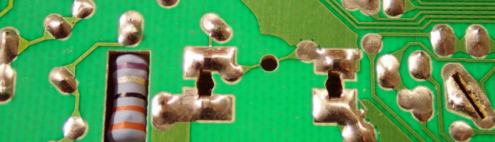
Flipping the board over, we see a lone power resistor sticking through, but also a rather original way to create a spark gap of a known size- by drilling a hole through a trace. The two terminals are the AC mains contacts, and the spark gap represents the first level of protection against transients. Judging by the size- it’ll take a few kV to jump across.

Neat way to create a spark gap across mains inputs. Note a smaller one under stamped numbers 011.
And now on to the fun parts- a block diagram as I see it:

High level system block diagram
We have a fairly standard transformer-less power supply, with MOV and spark gaps before and after the cap, followed by a rectifier and a Zener. The output voltage is diode Or-ed with the battery and fed into a Zetex/Diodes ZMR series 5V regulator. That 5V then supplies the logic. PIC16 runs the CO sensor and looks at its output, if the levels sensed exceeds the limit it enables the RE46C101 driver to sound an alarm and blink the red LED. The drive transistor for the sensing element is omitted. It is a bit odd that there is no fuse anywhere in the circuit, but it is possible that the power resistor is of a fusible type. Though how would that help if input MOV failed shorted is anyone’s guess. Another possibility is the use of a thin trace feeding the MOV as a fuse (see left AC mains terminal going north). Problem in that case is that once MOV fails shorted and takes the trace with it, there is no longer MOV left to protect the circuit, and no indication of that.
The sensor itself is described in great details in the manufacturer’s appnote. The basic idea is the use of SnO2 oxide, which when heated to a particular temperature absorbs oxygen and creates a barrier to electron flow. In the presence of deoxidizing gas such as carbon monoxide, density of Oxygen decreases, lowering the effective resistance of the sensor. The sensor contains a heater and the sensing element. The detector pulses the heater with a 1 second interval and then enables the sensing element and measures voltage across it a certain amount of time after heater activation.

Sensor details from Figaro datasheet
On a related note- Figaro is making a lot of very interesting sensors I never knew existed. Cooking vapors sensors anyone?
hi
i want to make set for detect Ammonia gas.
there is a same sensor for this application.
i want to make this set with TGS sensor.
is possible for you to send your set Schematic for me