Today we have a teardown of a Soviet calculator Elektronika MK 51( Электроника МК 51) for those familiar with the language. It was bought new in 1993, worked (sorta) for a few years and just drove me absolutely nuts with its lack of any reliability. The design is supposedly a clone of Casio FX-2500

Front view

Date code is 3/1993. Sign of new times: "free market price" line on the bottom. Older models had fixed price listed. The sign of the little dude in a circle points to Angstrem factory in Moscow. They've been making them since 1982 and all the way till 2000
Taking two screws out, the back cover (a stamped metal piece) is removed and we see the board, with obligatory red solder mask

Take it apart! Notice the recessed area in the plastic for the battery holder- it contains both 23xx type battery cutout and could also handle two smaller cell. The first version sold for 70 rubles, and the second for 67. Quite a lot of money back then.

Battery and main micro are recessed into the board
Taking a bunch more screws out, the board slips out of the case, leaving keypad and LCD in the plastic holder

Note the sliding power switch
Pretty standard buttons, relying on a membrane with conductive surface to make contact. Note the sliding switch contacts in the upper right. The hot melt plastic holding it was a very typical failure point. So were the conductive coatings wearing out on the rubber keypad .

Interesting lead frame package. The slide switch wipers were sliding over the pads in the lower left. Note the carbon coating on the Zebra strip and button contacts
The slide switch was a really weak point of the system. The spring contacts sliding over solder coated pads did not take long before intermittent connection developed, causing random reboots.

These used to wear out and short frequently, at least on mine

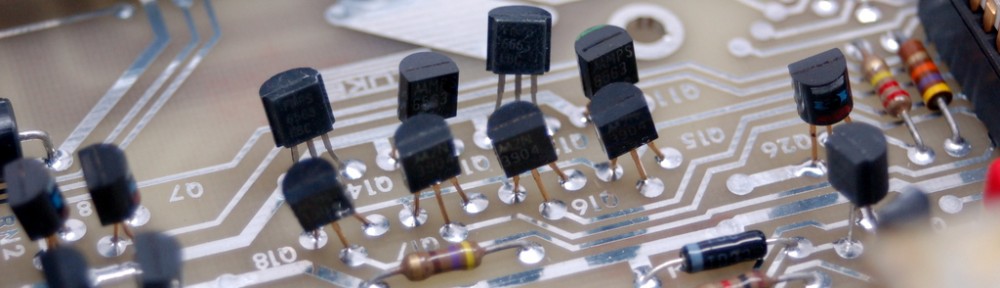
Another shot of the top of the board. The green part on the left is a 1.5uF cap. Resistor R2 was a part of the RC oscillator circuit, while R1 was a 100 ohm in series with the battery. . Note how solder mask is removed in large blocks, unlike modern boards where it separates pads
Moving on to the display (part number ИЖЦ2-9.7 with a 1992 date code), it’s a transmissive glass panel, with a separate polarizer film installed in the case in front and a reflecting sheet behind. Pretty standard Zebra strip (another source of many troubles in this model) connects things to the board:


ИЖЦ2-9.7 - LCD part number
And finally, for those curious, here is the schematic:

100 ohm resistor in series with the battery?
Update: I’ve attempted to power it and see what happens. Well, it does work, as long as somebody continuously presses on the back of the board near LCD Zebra!

The waveform on the RC oscillator resistor indicates a 75Khz clock