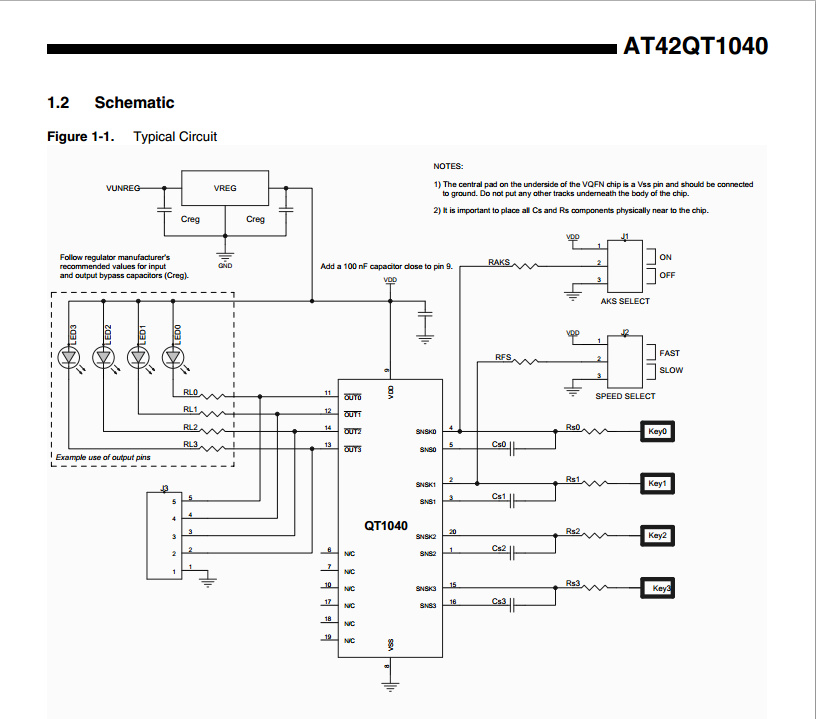
I happened to use an Atmel Qtouch chip in a project recently. The particular part was AT42QT1040, used in a fairly typical application- replacing four tactile buttons with four touch buttons. The chip is literally a “black box” that you give power, connect a few passives to the electrodes and in return you get four digital outputs representing the status of each key. No software to write, and is very simple. This particular feature came up very handy when a customer recently decided to switch from tactile to touch buttons mid-design. Since I was using Altium Designer on this project, the electrodes were essentially a freebie for me. I simply used Atmel Qtouch library, added the rectangular buttons into my schematic as components and synchronized to PCB. The sensor pads appeared in my layout. Done! All I had to do was go back to schematic a few times and in properties of the part adjust the dimensions of the pad to fit my board geometry. The design itself was essentially a reference design, with default values for the caps (0.01uF) attached to the sense pads.
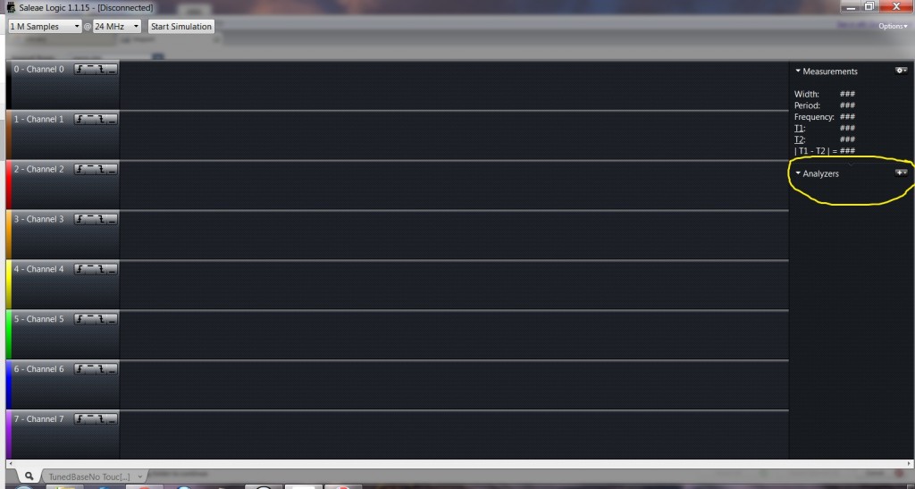
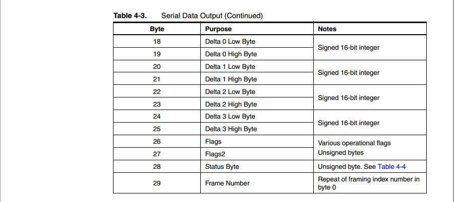
Once the boards came back and were assembled, I started testing. Sitting on a bench, my board could detect touches readily on all four channels. Now I needed to tune it to detect touches behind 1/8″ acrylic front panel. There are a few ways to do that. One is to keep increasing the values of the caps (within specified limits) until desired sensing distance is achieved. The other involves using a handy debug mode of the chip. If a cap across channel 3 (CS3) is shorted briefly (sub 5 seconds) on power up, the touch controller enters debug mode and starts streaming data on two output channels in an SPI-like fashion. Output 0 becomes Clock and Output 1- Data line.The data comes in 29 byte chunks, updated continuously. Getting the chip in debug mode was very easy, manually decoding 29 bytes of data on a scope- not much fun. That’s where Saleae’s excellent Logic 16 analyzer enters the picture. Configuration took a few seconds. After connecting the analyzer and starting the PC application, on the right hand side, I clicked on + and selected SPI from a dropdown list.
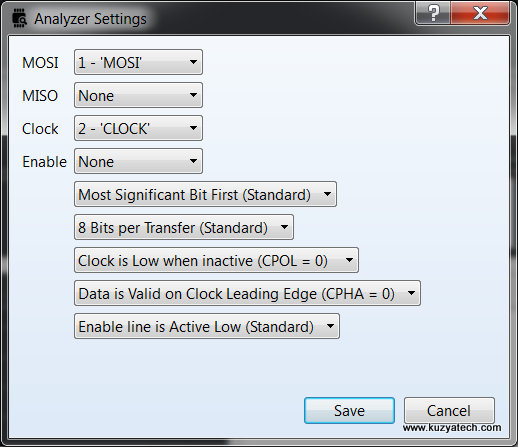
SPI analyzer is then configured as shown below, with the appropriate channels selected
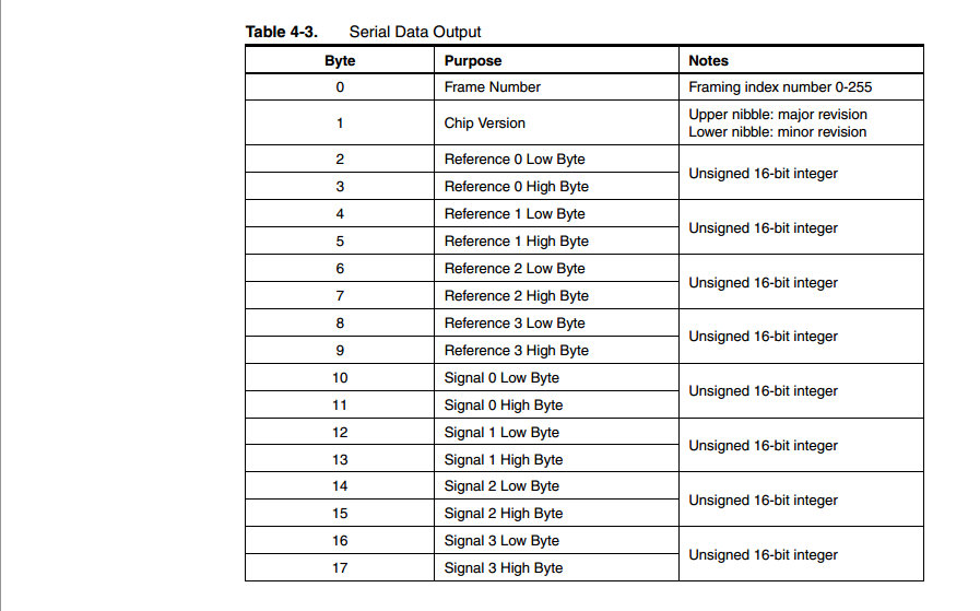
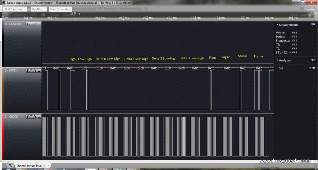
I also had to select “Display in Hex” under SPI settings. Now I was ready to decode data. Once I captured a block of data from the board, Logic 16 automatically decoded each byte, and I just needed to match them to the table in the datasheet
Now we have three sets of numbers: references, signal and delta. Reference shows what the chip calibrated as a number to compare the touch capacitance to. Signal is the measured value and delta is a difference of the two. In our case, there are no touches so signal and reference are identical. (They can also differ a bit within a threshold limit and still not cause a key press to be detected). From here, tuning is straightforward- we adjust caps on each channel to the desired sensitivity, and then check reported reference value. It should not exceed 1000 (per datasheet), and ideally be in a 500-600 range (per Atmel FAE). In my tests, I bumped one of the caps way outside the listed max of 22nF all the way to 47nf based on sensitivity alone. (A very subjective test!) What ensued was a bit hilarious- the key would stay pressed all the time whether I was touching it or not. Debug data showed reference in a 1200 counts range, way outside the suggested range. A check with theFAE confirmed that- with such a high value, I now had a proximity, not touch sensor! Quick cap replacement and now all references are now in 500-600 range. All caps ended up being slightly different values (18nF,18nF, 22nF, 33nf) which made sense: touch controller was at one end of the board and the four keys were lined up in a row. That way the traces kept getting longer from channel to channel, requiring larger sense cap to compensate.
In the end, being able to decode debug data and validate that all channels were in a “happy” range was much more effective than purely sensing distance tuning. I’d like to thank Saleae for creating such an easy to use and intuitive analyser.

