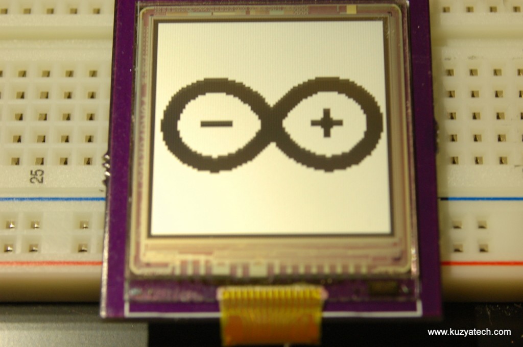
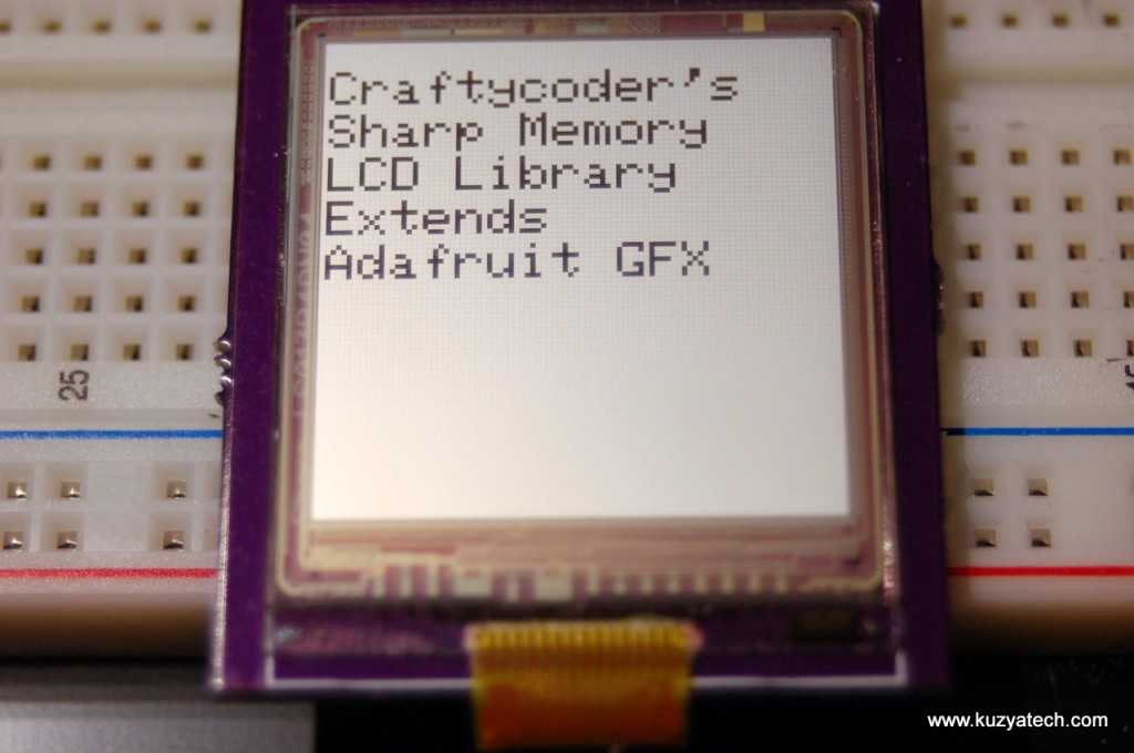
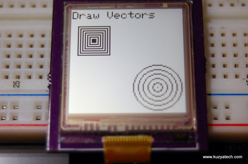
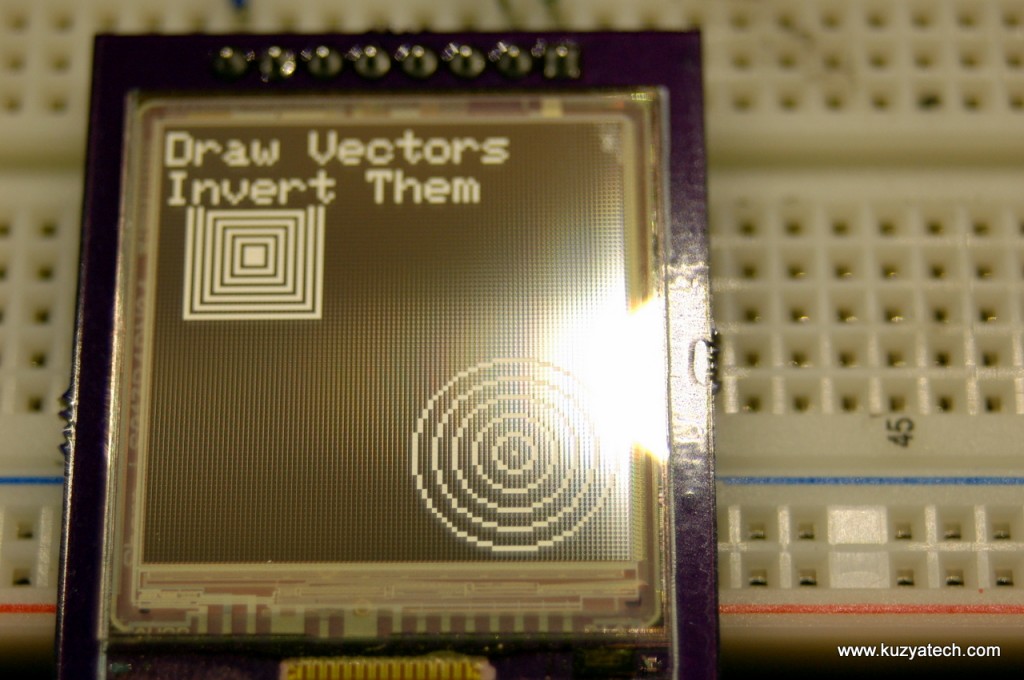
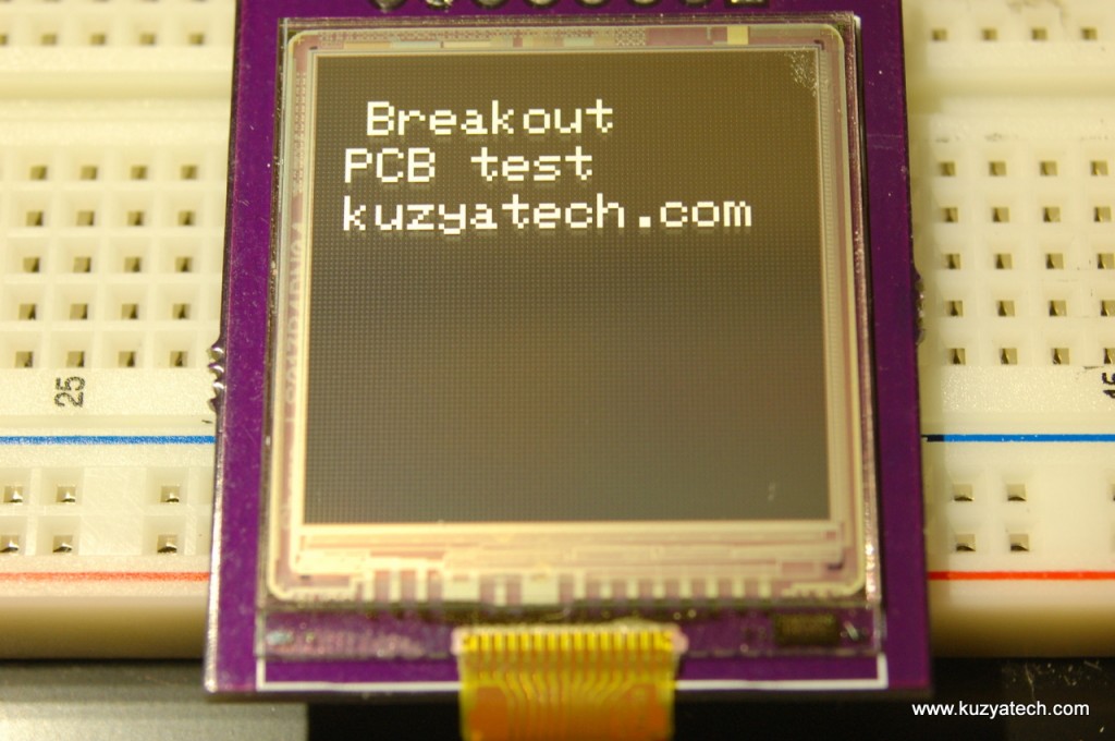
Sure, there is not much to test there- two connectors and a few caps. But the idea was to make the breakout so I can play with the display and see what I can design it in. For a while I stared at the datasheet, figuring out what it needs to be driven, then on a whim went to Google for an existing driver library for it. A library by craftycoder came up. It is based on Adafruit’s Arduino GFX library and includes an example that was more than enough to test the display. So I dug out my Arduino Uno and set things up:
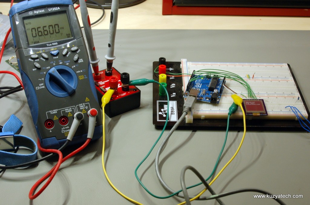
The setup was pretty simple: the display gets all signals from Arduino, including power. The part is used is a 5V display with 3V GPIO, but it appears to be 5V tolerant. So the lines are connected directly, with no level shifters. 5V line is going through EEVblog’s uCurrent in uA mode (which presents only about 10 ohm of series resistance – probably not necessary with a low power display, but it was a reason to play with it). And finally my Agilent U1252A DMM is looking at the output of the uCurrent, set to mV mode. This translates to a mV per uA display. The code example from craftycoder came up and ran with no issues.
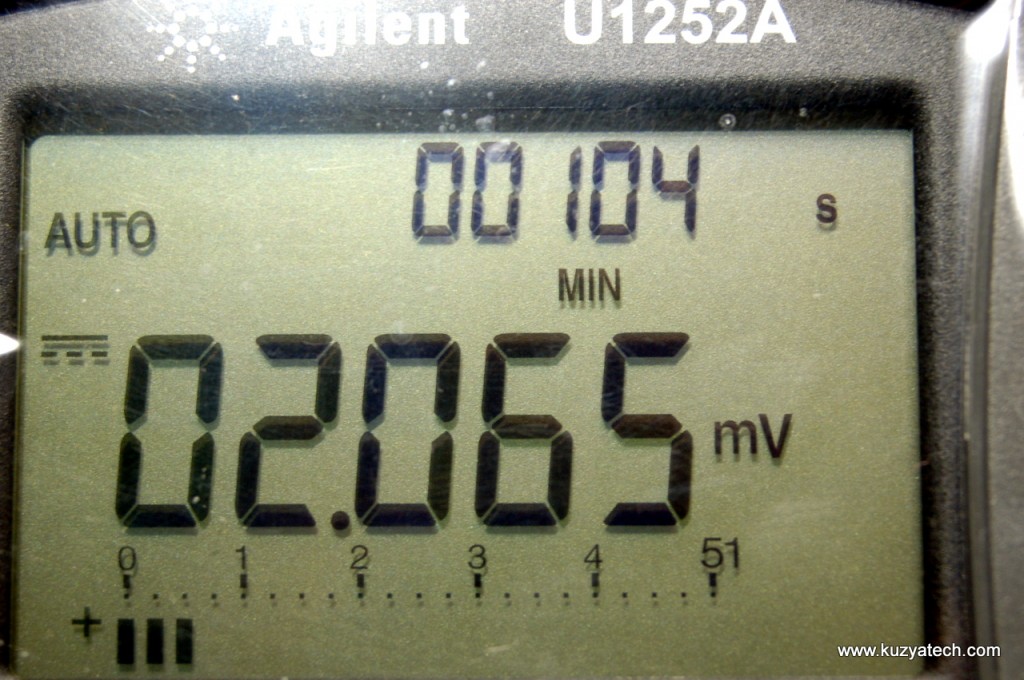
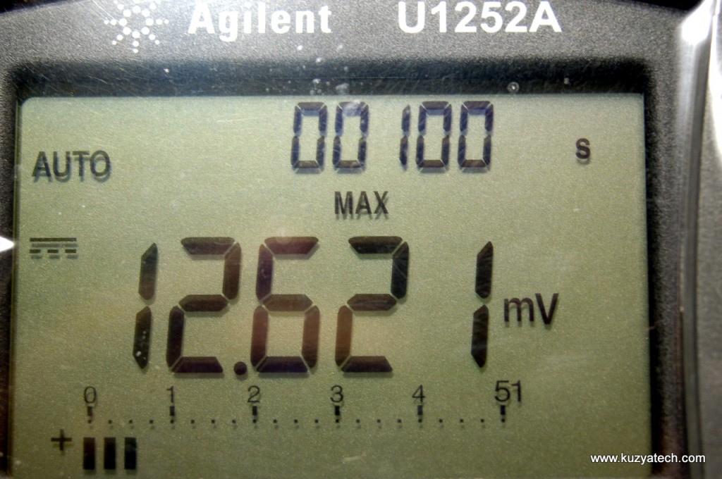
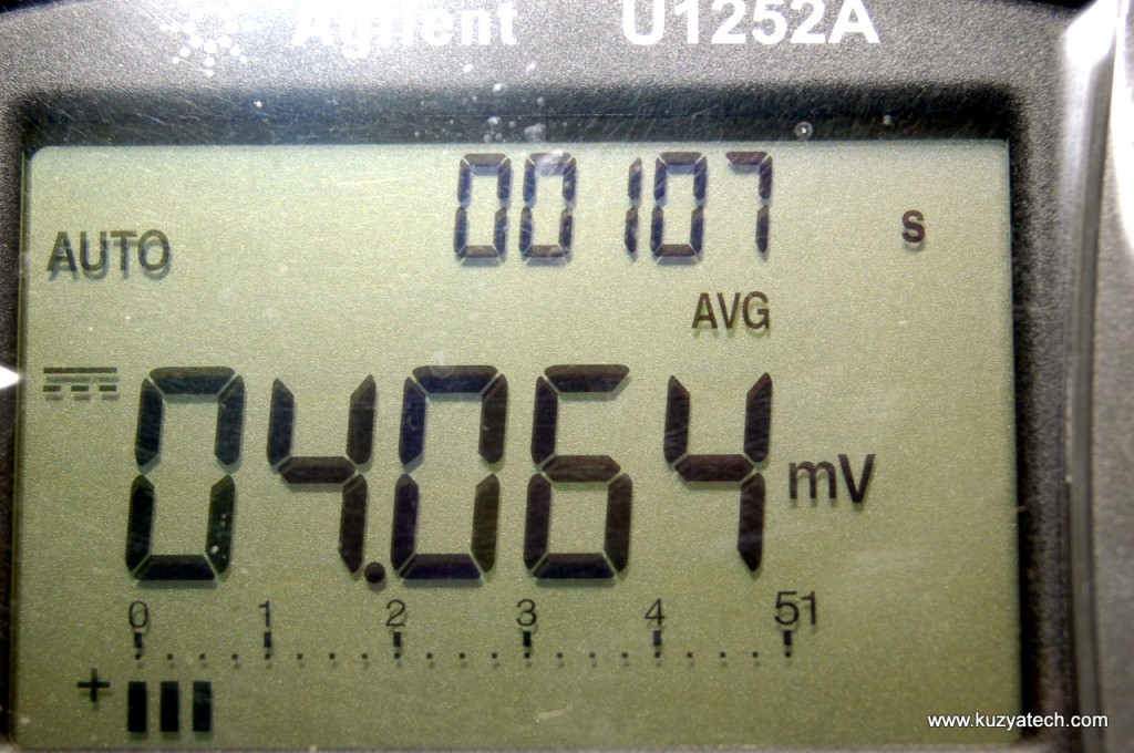
With things working, we can now check if this display is actually as low power as the datasheet claims. I’ve set my DMM to capture Min/Max/Average values and let it run for a bit:
So we see from 2uA to 13uA at 5V, with average around 4uA. The datasheet lists two numbers- 3uA and 6uA for a very specific display pattern and set of conditions, so it seems that the numbers are quite achievable. Now on to designing it into something cool. If there is some interest in the breakout board itself- let me know and I can make it available reasonably cheap.

