Sharp Memory LCD Breakout A2

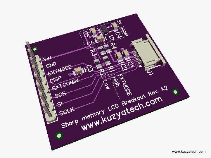
This is a simple breakout board for Sharp’s Memory LCD display family (LS013B4DN02, LS013B4DN04, LS013B7DH03, LS013B7DH06LS027B7DH01 and LS044Q7DH01). Those are the parts known at the time of the writing, though more models are coming out all the time. So far Sharp’s been keeping very consistent interface and there is a fairly high chance the board will work with all of them. In a table below is a list of displays I am aware of on the US market. Models needing 5V boost are marked accordingly.

The board brings all pins to a 0.1″ header and provides necessary caps and resistors. Revision A2 adds an optional boost converter for those wanting to run 5V display from sub 3.3V supply which is needed on color version, 2.7″ and larger screens and also some of the older ones.The footprints are there, but parts are not populated to save cost on the base version. A version with boost is now also available. This is an open design under CC BY SA license.

Continue reading

Solving “range anxiety” problem for my smartphone (well, almost)

As some of you know, I’ve recently traveled to Boston for the ESC/Design East conference. While that was fun, what quickly became a problem was my phone’s limited battery life. I’d leave in the morning with full charge, and by about 4PM each day it’d be asking for a charger. Normally it’s not a problem, except when you are in a new city and relying on your phone as a your navigation aid. There are obviously commercial solutions- a spare battery or a rechargeable battery pack or theOSHW ones such as Adafruit’s MintyBoost.  MintyBoost was the closest to what I was looking for, but still not quite it. So I set out to make my own. Continue reading

First product for sale- Sharp Memory LCD breakout

I have a few of the LCD breakout boards available for sale.

Schematic diagram is here .

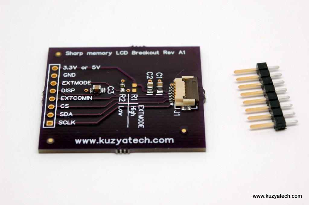
Note: the header is included but not soldered, to make life easier in case you need to run wires to the board instead. Sharp LCD is not included. You can get the 5V version (LS013B4DN02) from Mouser. Part number is 852-LS013B4DN02. The boards were tested with Arduino Uno driving the LCD directly with 5V IO. That seems to be fine for the display according to the Sharp Datasheet.

First solder the header or wires as needed, then attach the display using a small piece of double sided tape and connect the flex. See my previous post for pictures on how a fully assembled board should look like, and this post for testing details

Connections for Arduino  :

Breakout pin Arduino pin Breakout Pin Arduino  Pin
1 SCLK 13 6 EXTMODE 4
2 SI 11 7 GND GND
3 SCS 12 8 VCC 5V
4 EXTCOMIN 3
5 DISP 2

Shipping is via  USPS First Class Mail. Items in stock usually ship the next business day ARO. Allow a week or so for delivery in the US


Testing Sharp LCD breakout board

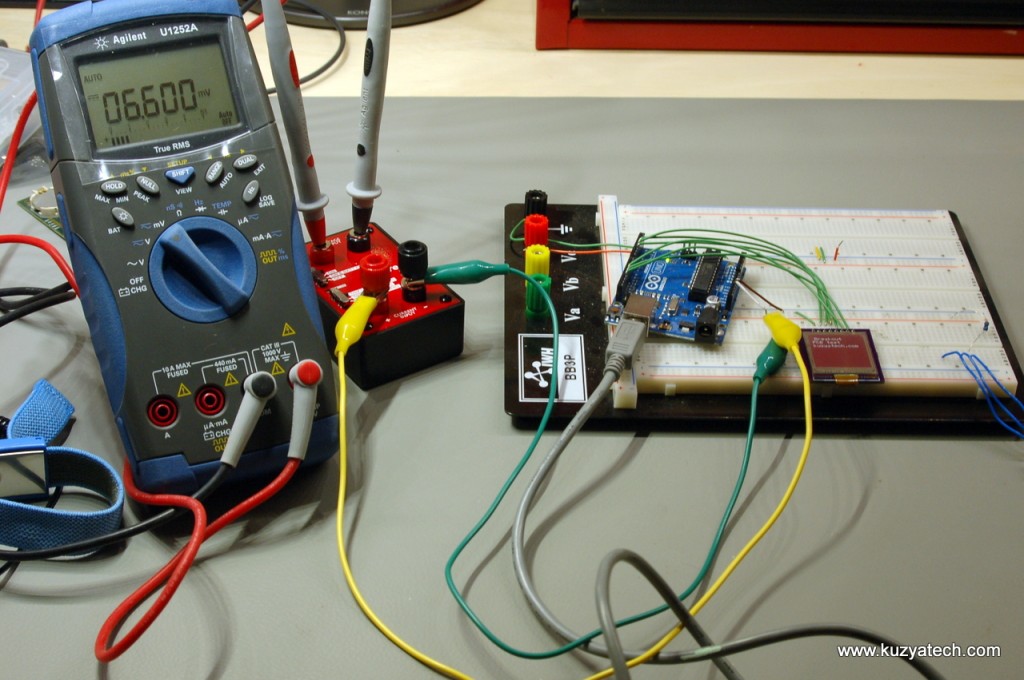
Sure, there is not much to test there- two connectors and a few caps. But the idea was to make the breakout so I can play with the display and see what I can design it in. For a while I stared at the datasheet, figuring out what it needs to be driven, then on a whim went to Google for an existing driver library for it. A library by craftycoder came up. It is based on Adafruit’s Arduino GFX library and includes an example that was more than enough to test the display. So I dug out my Arduino Uno and set things up:

Breadboard, Arduino Uno, uCurrent from EEVblog and a DMM.

Continue reading

Sharp Memory LCD breakout- boards arrived

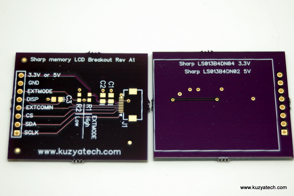
My boards from OSH arrived a while back, so here are some pictures.  The next step is getting the code running to test the display, though I may try feeding it some serial  goodness from Bus Pirate as a test. So far it appears that the first test run of DipTrace tools and OSH Park service went pretty well!

Bare boards from OSH Park, in their requisite color! Both sides look pretty good.

Continue reading

Atmel QTouch tuning using Saleae Logic16

I happened to use an Atmel Qtouch chip in a project recently. The particular part was AT42QT1040, used in a fairly typical application- replacing four tactile buttons with four touch buttons. The chip is literally a “black box” that you give power, connect a few passives to the electrodes and in return you get four digital outputs representing the status of each key. No software to write, and is very simple. This particular feature came up very handy when a customer recently decided to switch from tactile to touch buttons mid-design. Since I was using Altium Designer on this project, the electrodes were essentially a freebie for me. I simply used Atmel Qtouch library, added the rectangular buttons into my schematic as components and Continue reading

OSH Park rules for DipTrace

In response to a few requests, here is a design rules (DRC)  file (OSHPark.zip) I created  when ordering boards from  OSH Park. To load them unzip the file and in Layout program, select Route- Load Rules.  Note that the numbers are based on a somewhat limited information available. (For example I do not have data on the maximum hole size) The settings are as follows: Continue reading

TI Launchpad Booster Pack footprint library for DipTrace

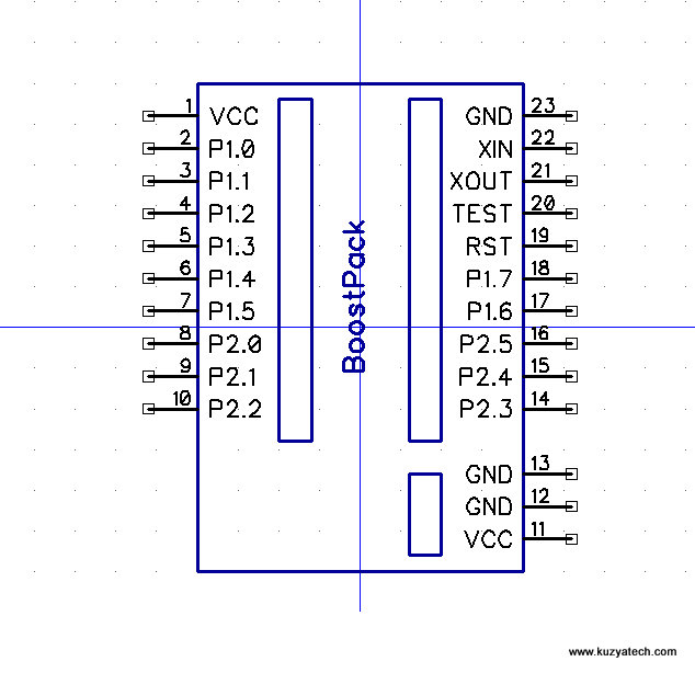
Today’s post is a small DipTrace library i created for some TI Launchpad Booster Packs I am working on. It is modeled after a similar Eagle library posted on www.43oh.com forum.

There are two schematic symbols and three footprints:

Full size covers the whole Launchpad footprint

Continue reading

Sharp Memory LCD breakout

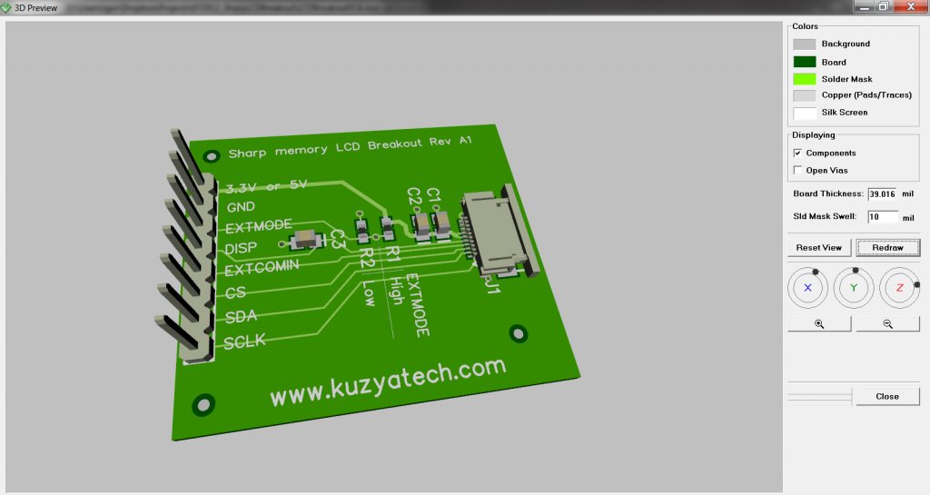
As promised, some 3D rendering pictures of the Sharp Memory LCD breakout board I just designed in DipTrace. The learning curve is definitely very short. It’s not always obvious were a certain option or menu item is hiding, but nothing some Googling can’t fix. Overall feel of the tool is that they started with basic functionality and added just enough higher end features to cover the majority of typical design needs. I like it so far.The 3D models are not exact, since I am using what I could find for the parts. Not all vendors are nice enough to provide their models just yet.

The components side

Continue reading