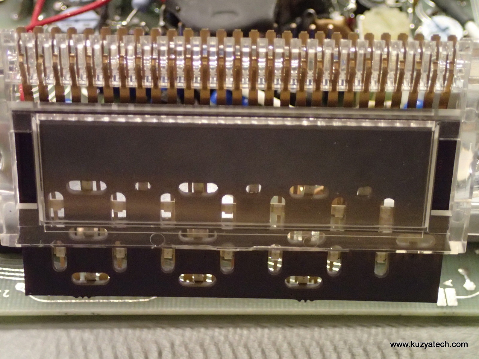
A while back I did a teardown on a vintage multimeter- Weston 6000. The 38 years old LCD was dead, but otherwise I saw signs of life in the meter. So I figured I’d try recreating the display using modern components. I measured the display first to see if I can find something off-the-shelf to fit. No luck, the module was wider than typical 3.5 character displays. I was also trying to reuse the existing support and connection systems. At the same time I stumbled on a blog post “A Very Unique Fluke 8060A” at Mr Modem Head about using LEDs in a similar application. The idea was that modern LEDs can be driven at current levels similar to the LCD segment refresh current. That seemed doable, so I went down that path. The original poster handwired the LEDs, but I figured Oshpark is a better approach. Reusing original holder meant not enough clearance for off-the-shelf 7 segment SMT displays, so it was down to discrete LEDs. The display pinout was extracted after spending a lot of quality time staring at the original display with a flashlight and a magnifying glass. I then created schematic and board layout in Altium as it was an easier way to handle complicated geometry vs my usual tool of choice- DipTrace.
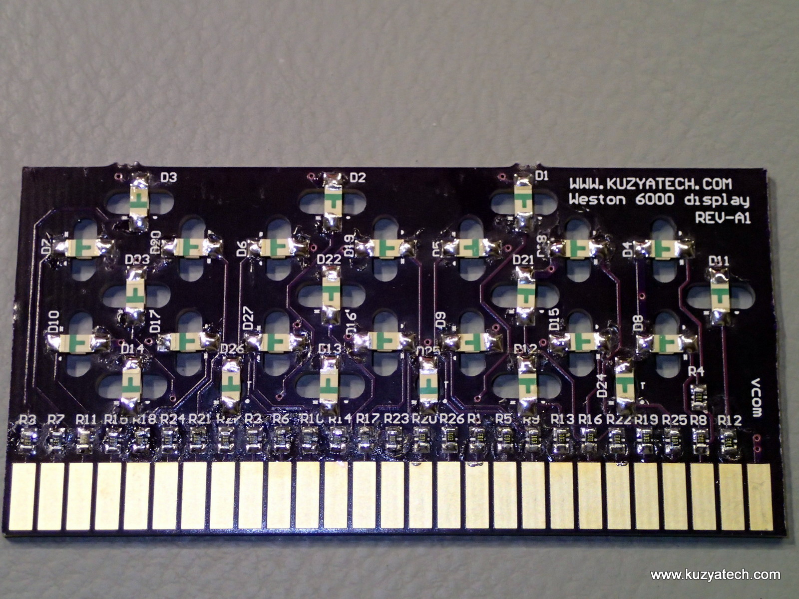
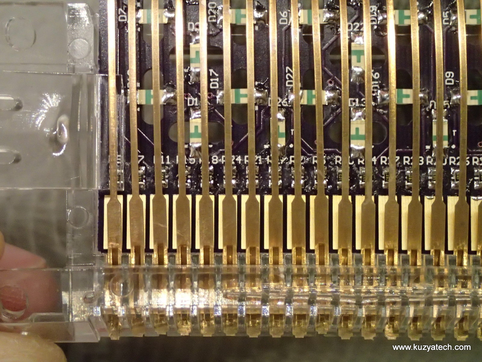
I’ve used reverse mounted LEDs looking through the board slots.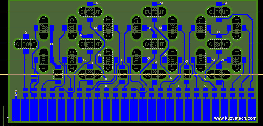
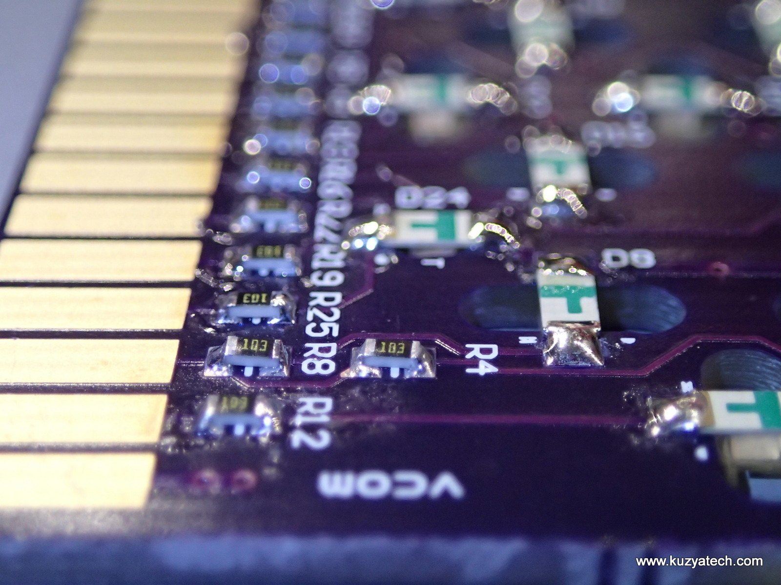
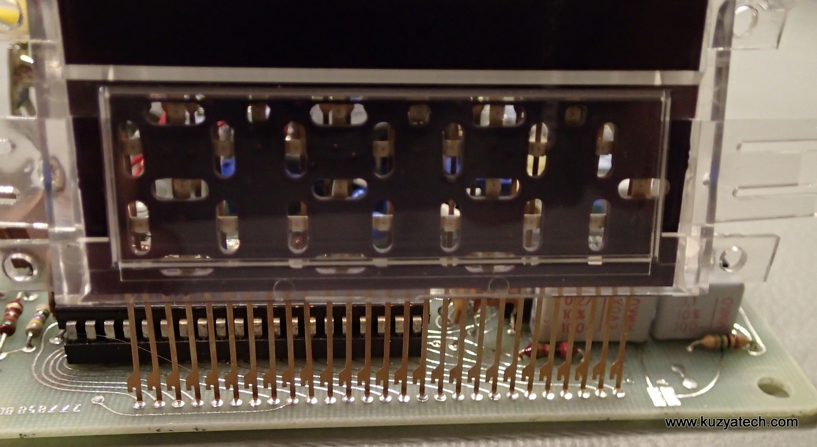
Boards came back very quickly and I built one. Mechanical fit was perfect
Conclusion:
The display fits and works, mostly. The single LED per segment and lack of diffusion do not help seeing the numbers instead of collection of dots. Drive currents still need adjustments and it is not clear that I got the pinout 100% correct since not everything displayed makes sense. So at the moment this project is more of a show-off than a useable display. To be continued

What do you use to solder so accurately? Approximately how long does it take per contact, and how long does it take to set up? My soldering seems way to slow, so I wanted to compare it to others…
Using good iron helps- Metcal or clones like Thermaltronics, and it’s usually a few seconds per point