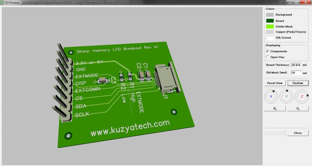
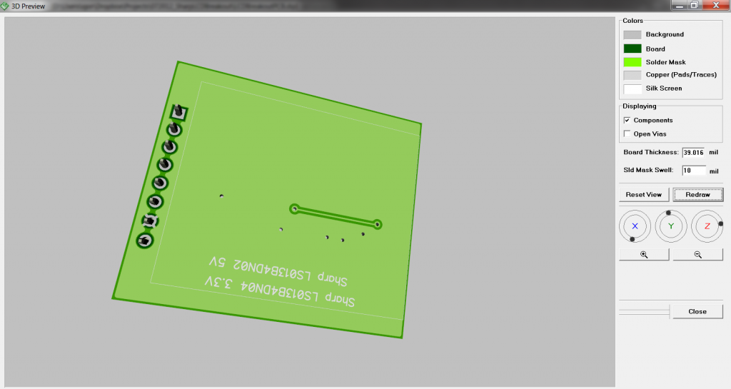
As promised, some 3D rendering pictures of the Sharp Memory LCD breakout board I just designed in DipTrace. The learning curve is definitely very short. It’s not always obvious were a certain option or menu item is hiding, but nothing some Googling can’t fix. Overall feel of the tool is that they started with basic functionality and added just enough higher end features to cover the majority of typical design needs. I like it so far.The 3D models are not exact, since I am using what I could find for the parts. Not all vendors are nice enough to provide their models just yet.
The idea is to mount the display with a double sticky tape on one side and run the flex over the other side. That way the display and the FPC connector are all on the same mechanical support plane and the cable is not stressed. Electrically, the design should work with both 5V and 3.3V displays, I (woops) did not notice the difference when ordering mine and ended up with a 5V version ( LS013B4DN02 vs LS013B4DN04 ) . The GPIO is still 3.3V , but it needs a 5V supply. Sharp does list a few boost converters to generate 5V from 3.3V, but their quiescent currents easily exceed power demands of the display. It’d be silly to bother! Oh, and the amount of copy-paste errors in their datasheets is a bit strange. The whole section about powering the display from a 3V supply through a charge pump is kept verbatim in a 3V version?!


Hi,
very nice design! Could you please tell me, which part in Diptrace you used for the FPC connector?
Best wishes
I think I just built one myself- its pretty easy in diptrace