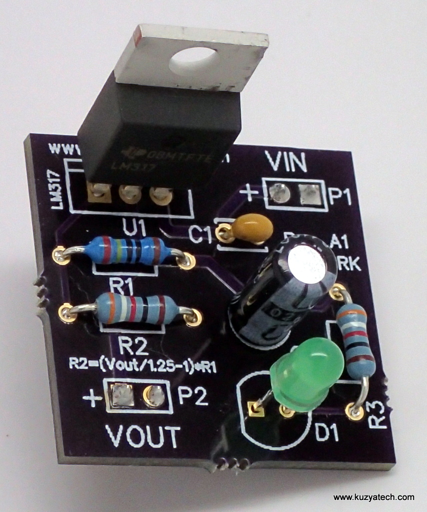
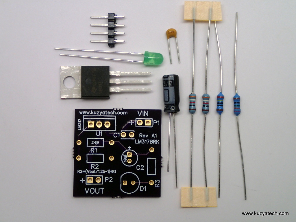
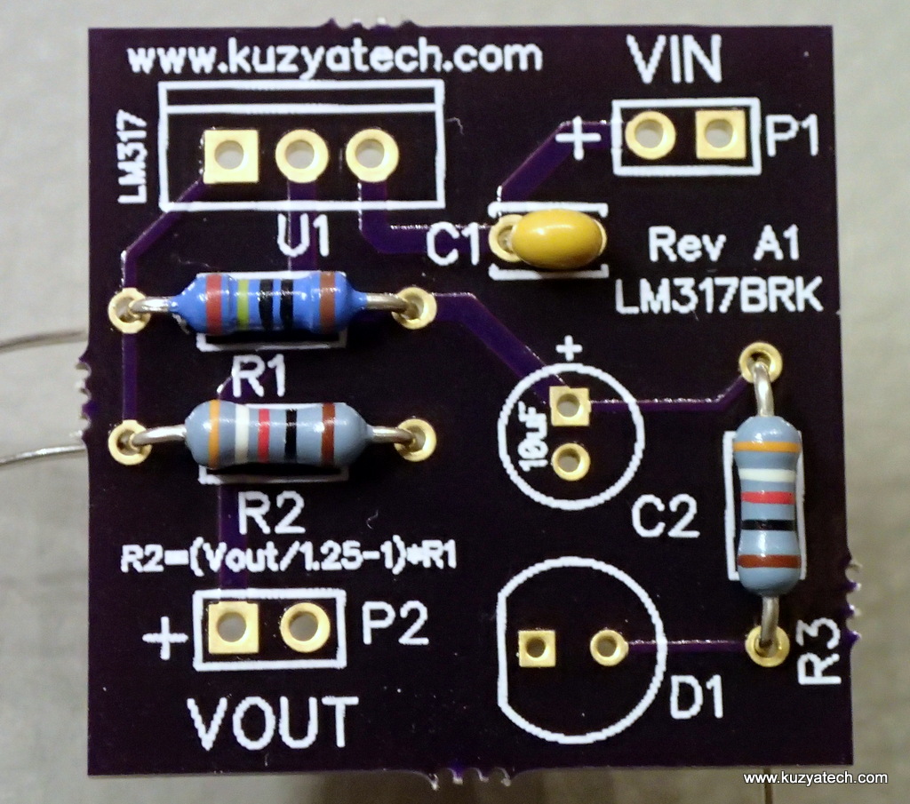
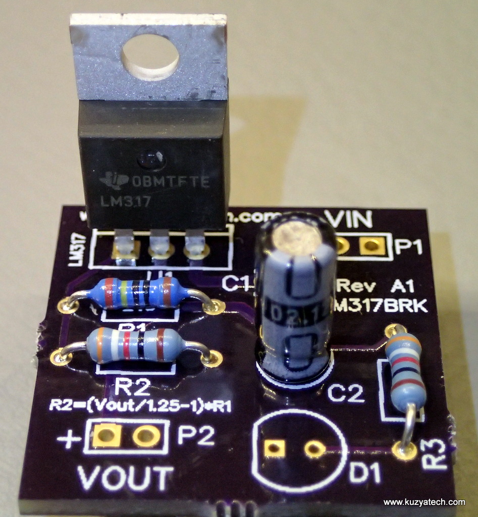
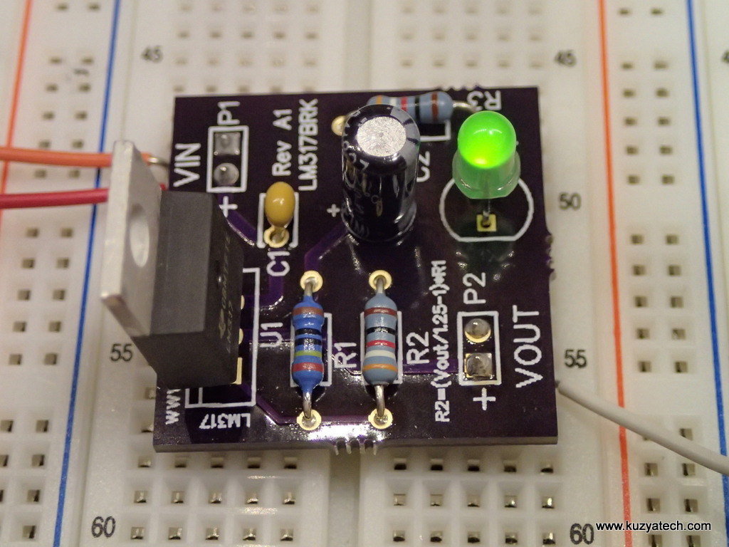
Here is something I got tired of making every time so I designed a board for it! It’s a simple LM317 power supply breakout:
The board is available as a kit in my Tindie store.
The schematic is here. You get all the parts shown below plus an extra 1.3k resistor for the new 8V output option
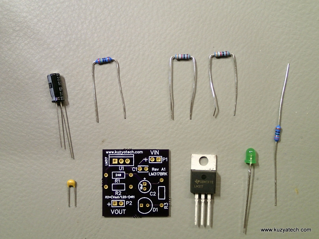
The assembly is pretty simple. First pick the value of R2 for the output voltage you need using a handy formula on the board for R2 or the table in the schematic. I’ve included three R2 values in the kit- one for 8V (1.3k) ,one for 5V ( 715 ohm) and one for 3.3V (392 Ohm). Next prepare all resistors by bending their leads with a pair of pliers:
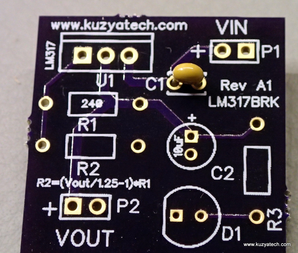
Next install the small yellow cap (marked 104) into C1 spot, bend the leads on the back and solder.
Repeat with resistors R1, R2 and R3
Install U1 in the orientation marked. Next install C2. The plus is marked on the board, but the electrolytic capacitors are usually marked with the negative band. Make sure it goes to the hole without +:
Finally install LED- the flat edge should match that on the silk and pin headers if desired:
You are done. Now you can trim the leads and test the board.
Operation:
The input voltage range is 3V to 40V, and the output can be set between 1.25V and 37V. Output current is limited to 1.5A, and depends on the power dissipation in the chip and available cooling. You would have to look at the voltage difference across the chip times the current and times the thermal resistance from junction to ambient (in this case 19C/W). As an example at 12V in and 5V out at 1A you’d be dissipating 7W. That would result in a junction temperature rise of 7×19 or 133 C rise above ambient- talk about toasty! So if you need that much power- use a heatsink that will lower thermal resistance sufficiently! The IC is near the edge of the board and can be mounted on one if needed.

